2-26 Published 08-25-09, Control # 077-04
HYDRAULIC SYSTEM RT9130E SERVICE MANUAL
Procedure I - For Checking Swing Valve
Work Port Relief Pressure
1. Remove cap and install pressure gauge on swing valve
inlet test port (Figure 2-13).
2. With the swing lock Engaged and the engine running at
FULL RPM, swing LEFT and adjust “A” port swing relief
to 17.2
± 0.4 MPa (2500 ± 50 PSI).
3. With the swing lock Engaged and the engine running @
FULL RPM, swing RIGHT and adjust “B” port swing
relief to 17.2
± 0.4 MPa (2500 ± 50 PSI).
4. Remove pressure gauge from the swing inlet test port
and reinstall cap.
Procedure J - For Checking Relief Setting
for Counterweight Supply Control Valve
1. Remove cap and install gauge on load sense relief test
port on main directional control valve (Figure 2-14).
2. Operate the counterweight directional control valve by
fully raising or lowering the counterweight cylinders.
Adjust the counterweight removal directional control
valve load sense relief valve to 26.2
± 0.4 MPa (3800 ±
50 PSI).
3. In the cab, press the luffing extension switch to ON and
the luffing raise/lower switch to LOWER in the LH
armrest. Adjust the luffing extension “B” port relief valve
to 10.0
± 0.4 MPa (1450 ± 50 PSI).
4. In the cab, press the cab tilt switch to the RAISE position
and adjust the cab tilt “A” port relief valve to 17.2
± 0.4
MPa (2500
± 50 PSI).
5. In the cab, press the cab tilt switch to the LOWER
position and adjust the cab tilt “B” port relief valve to 17.2
± 0.4 MPa (2500 ± 50 PSI).
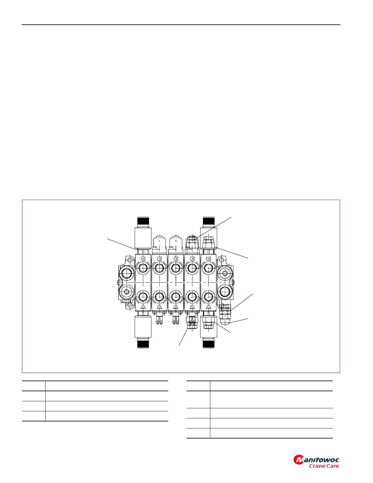
FIGURE 2-14
Counterweight Removal Directional Control Valve
1
2
3
4
5
6
7
Item Description
1 Luffing Extension Relief “B” Port
2 Counterweight Pin Relief ‘B” Port
3 Cab Tilt Relief “B” Port
Item Description
4
LS Relief Valve Adjustment: Turn Screw
Clockwise to Increase Pressure
5 Remove Cap
6 Cab Tilt Relief “A” Port
7 Counterweight Pin Relief “A” Port