Published 08-25-09, Control # 077-04 2-23
RT9130E SERVICE MANUAL HYDRAULIC SYSTEM
Procedure C - For Checking Swing Brake
Supply Pressure
1. Remove cap and install pressure gauge on swing brake
supply valve test port (Figure 2-9).
2. With the engine running at idle, adjust the swing brake
pressure reducing valve cartridge (Figure 2-8) to 1.7
+0.4/-0 MPa (250 +50/-0 PSI).
3. Remove pressure gauge from the test port and reinstall
cap.
Procedure D - For Checking Service Brake
and Air Conditioning Circuit Relief Valve
Pressure
1. Disconnect pressure hose at the dual accumulator
charge valve “P” port (Figure 2-11) and attach a
pressure gauge.
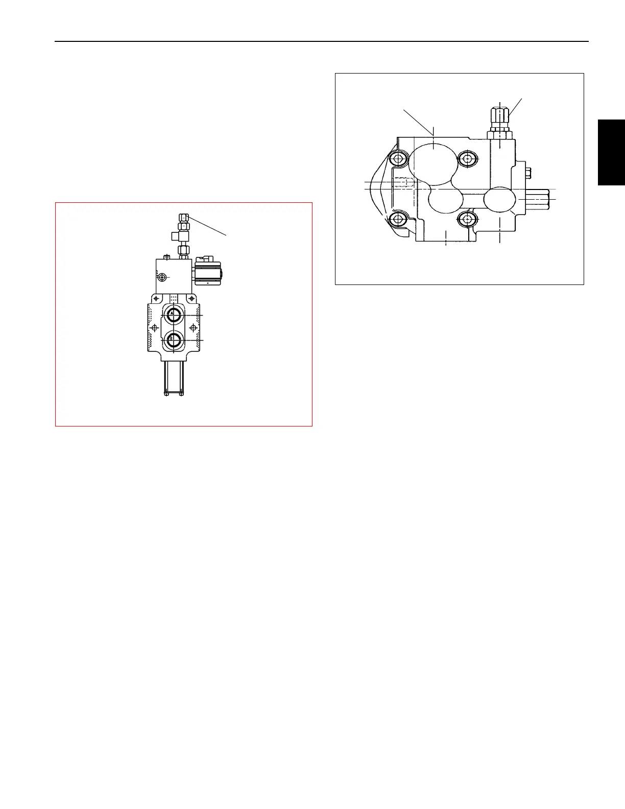
2. Run the engine at idle (950 RPM), for only 5 - 10
seconds since the flow will be “Hot Looped”. Check the
pressure. Adjust the service brake and air conditioning
relief valve in the pump mounted on the back side of the
charge pump (Figure 2-10) to 20.7
± 0.4 MPa (3000 ± 50
PSI). If this step needs to be repeated, make sure the
pump is Not Hot to touch. If it is, let it cool before
proceeding.
3. Remove pressure gauge and reconnect the pressure
line.
Procedure E - For Checking Service Brake
Dual Accumulator Charge Valve Pressure
Limits
1. With the engine off, discharge all of the pressurized oil
stored in the accumulators by depressing the service
brake pedal on the cab floor 4-6 times.
2. Install a pressure gauge at the service brake dual
accumulator charge valve “A1” pressure test port
(Figure 2-11).
3. Start the engine. The charging valve will immediately
start to charge the accumulators. Watch the pressure
gauge. The high charge limit pressure should read 19
+0.4/-0 MPa (2750 +50, -0 psi) when the valve stops
charging. If adjustment is required, proceed to step 4. If
not, go to step 5.
4. Turn the engine off, remove all the fittings in the tank port
on the dual accumulator charge valve, and plug the tee.
Using a wrench, turn the socket head screw inside the
tank port clockwise to raise the charge limits or
counterclockwise to lower the charge limits. Turning the
screw a full turn will change both limits by approximately
1.7 MPa (250 psi).
5. With the engine running, bleed off the hydraulic pressure
stored in the accumulators by pushing the service brake
pedal on the cab floor until the gauge reads about 16.5
MPa (2400 psi). Listen to hear when the service brake
dual accumulator charge valve starts to recharge. Push
the service brake pedal once more; the valve should
start to recharge. Watch the pressure gauge. The low
charge limit should not be less than15.2 MPa (2200 psi)
when the valve starts to recharge. If the low charge limit
is 15.2 to 16.2 MPa (2200 to 2350 psi) proceed to step 7.
If adjustment is required, proceed to step 6.
Swing Brake Supply
Test Port
7128-2
FIGURE 2-9
Swing Circuit Series-Parallel Valve
Relief Valve
Suction Port
FIGURE 2-10
Service Brake and Air Conditioning Pump (Rear View)