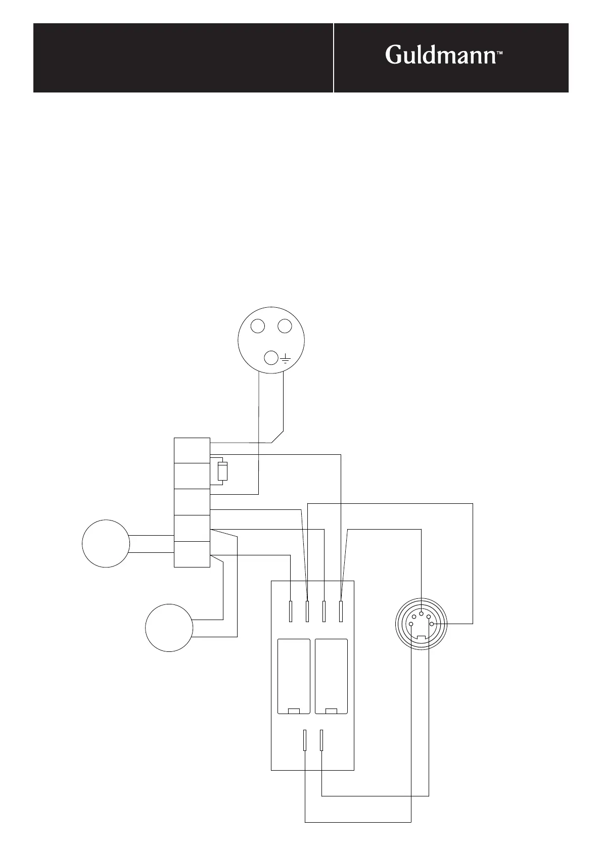
A
B
C
D
E
F
Blue
Red
White
Green
Charge
.2
Motor
2
Brown
Blue
1
2
3
4
5
.
L
Blue
Brown
Battery plug
Blue
Brown
Motor
1
© Guldmann GB-1394/11/08
59
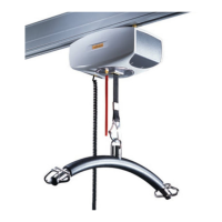
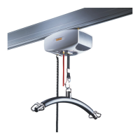
4. electrIcal connectIon
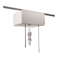
The room-covering drive motor
is installed as described:
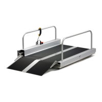
• Travelling trolleys are placed in the two parallel rails
so that the motors/covers face inwards towards the
traverse rail.
• The battery box is fitted/hooked on at the top of the
traverse rail.
• Position two charging stations, one in each parallel rail.
One for charging the hoist and one for charging the
room-covering drive motor (the battery pack).
• The two drive motors/traverse travelling trolleys must
be connected with each other in parallel. The wire (not
included) should be drawn through the traverse rail from
position 1 (blue) and position 2 (red) across to the other
drive motor and connected to the motor. It is necessary
to remove the plastic covers.
• The battery pack must be connected to the terminal
board in the drive motor, + in position 4 (green) and
– in position 3 (white).
• The three-pin plug to the battery pack must be
connected with + on N and – on L.
• The wire on the infra-red receiver should be plugged
directly into the plug on the traverse travelling trolley and
the infra-red receiver placed on the plastic cover on the
traverse travelling trolley.
• If the motors run in different directions, the wires
connected to the terminal board for motor 2, positions 1
and 2, should be reversed.
Traverse drive motor