A
B
C (X2)
D (S1)
E (X1)
D: Fuse
C: AC 24V
E: Timer PC board
B: Motor
A: Hand control
© Guldmann GB-1394/11/08
61
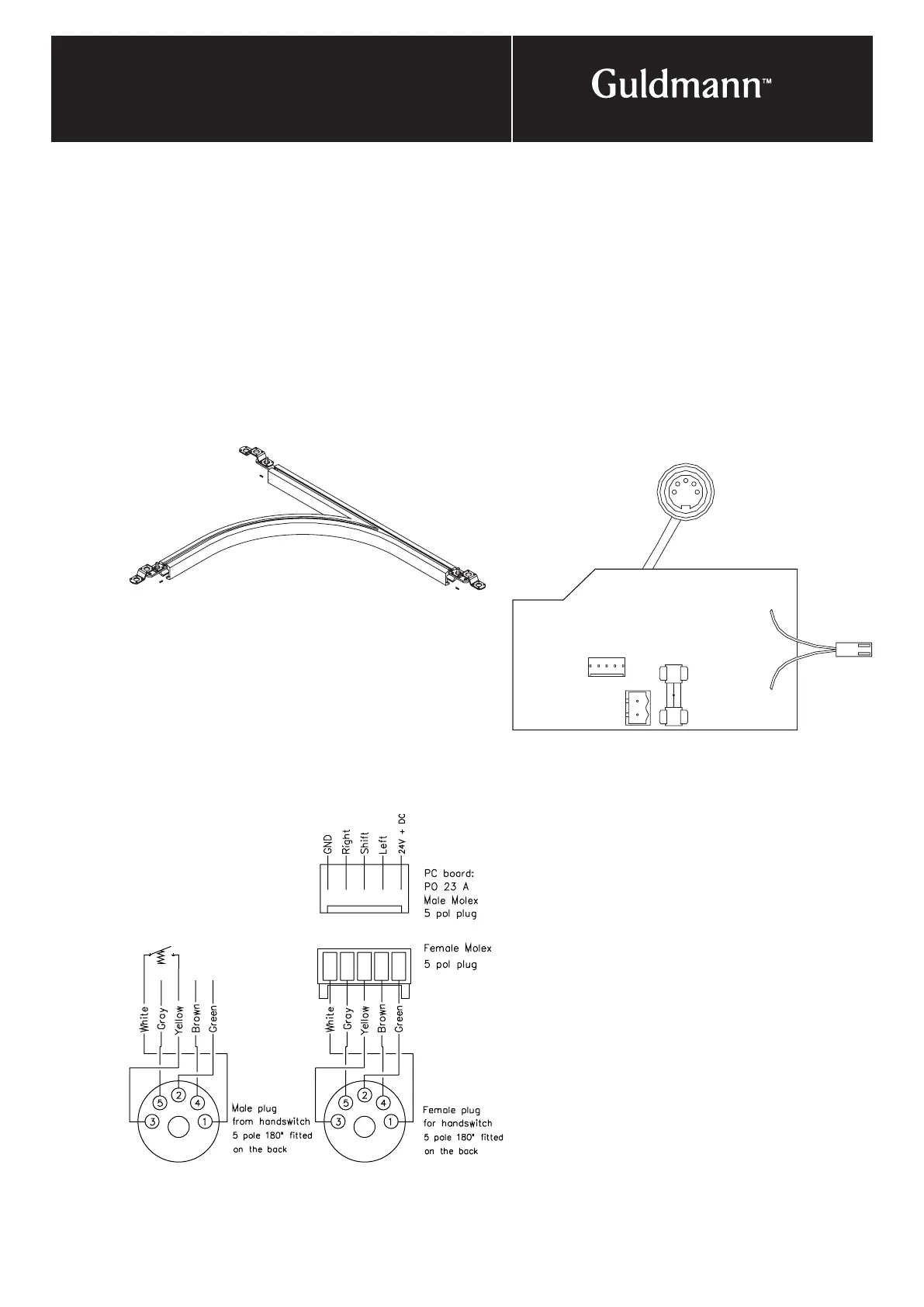
4. electrIcal connectIon
Switch track
Switch tracks are used where there is a need to lead the
rail in several directions. Manual and electrical switch
tracks are available.
The switch tracks are installed as described:
• The switch track is always fitted with three ceiling
brackets at the ends.
• Manual switch tracks – rail for cord drive can be
removed, and the two reel brackets are fitted directly
to the ceiling.
• Electrical switch track – the transformer is fitted by
leading the wires into the top of the switch track and
connecting it to the PC board of the connector X2.
How the wires are orientated is not important.
• The manual control is connected on the outside of the
electronics box.
• Check that the switch track functions properly every time
the cords/hand control is activated. The ”tongue” must
never make contact with the other components.
• The hoist must be able to run freely through the switch
track.