A
B
C
D
E
F
Blue
Red
White
Green
Charge
NR 934001
Motor
1
P1
1 2
2
X1
X3
NR 934036
Motor
2
Brown
Blue
Brown
Blue
A
B
3
4
© Guldmann GB-1394/11/08
60
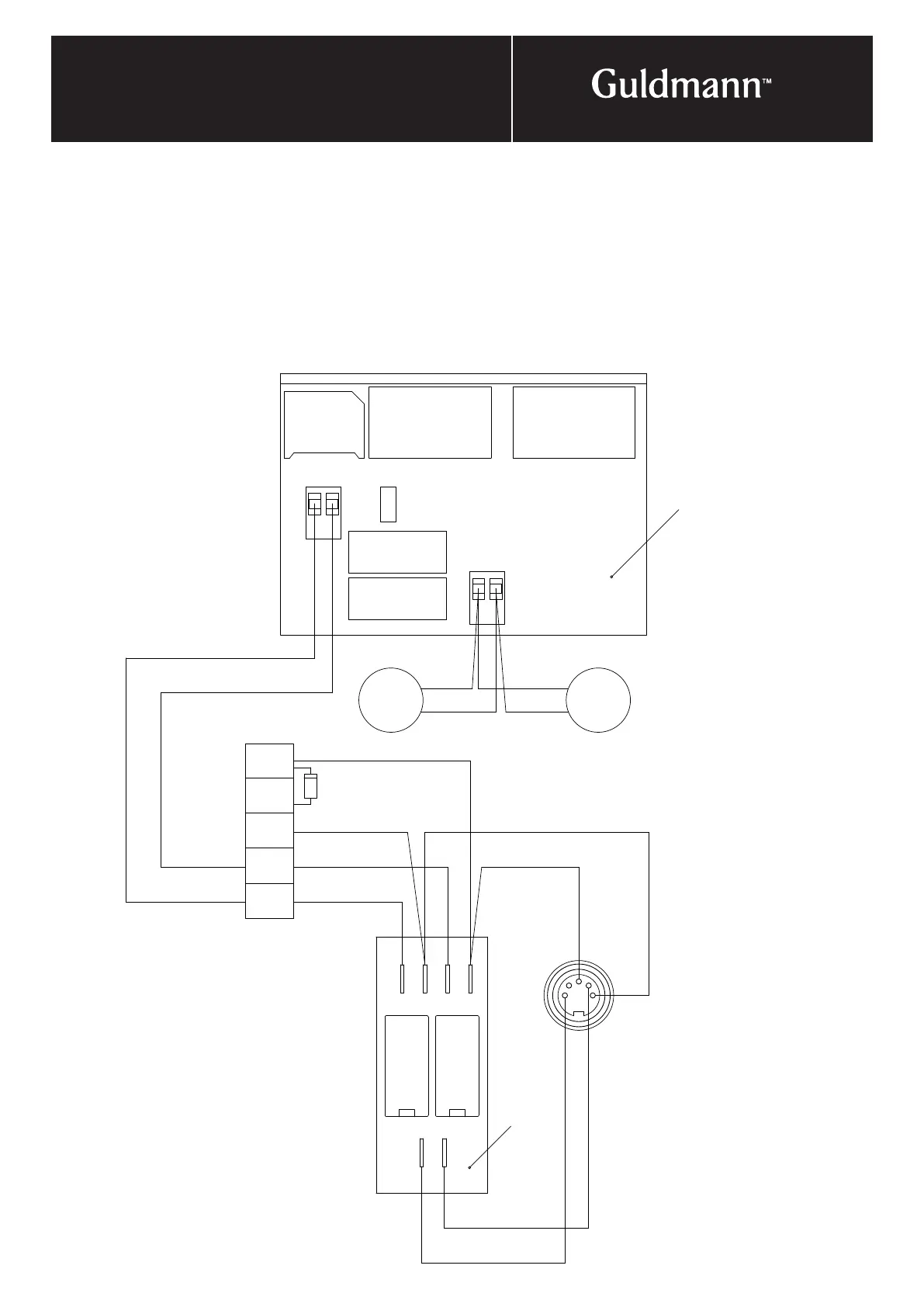
4. electrIcal connectIon
Installing the motor control PCB in the DC traverse
travelling trolley
• Put the motor control PCB into the cover on motor 2.
Two wires, measuring 2 x 0.75 mm² must be drawn
through the traverse rail and connected to the motor
control PCB (A) and motor 2 to the main PCB (B).
• Connect the motor control PCB (A), position X1 to PCB
B via positions 1 and 2 on the terminal board.
• Remove the brown and blue wires from motor 1 from
terminal boards 1 and 2 and connect them to motor 2,
position 3 on the motor control PCB via the wire in the
traverse rail.
• Speed can be regulated by turning P1 anti-clockwise.
• If the motors run in different directions, reverse the wires
to motor 2 in plug X3.
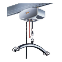
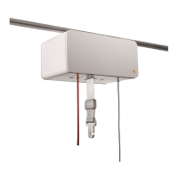
Traverse drive motor