© Guldmann GB-1394/11/08
62
4. electrIcal connectIon
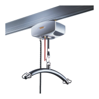
Combi-lock
CL3 electrically operated
Comprises:
• Safety lock for fixed rail
• Safety lock for traverse rail
• Motor unit
The Combi-lock is used at the transition between a
room-covering rail system and a single-track rail system
to provide optimum safety when the two rail systems are
used together.
The function of the Combi-lock:
Engagement: A tongue is inserted to link the traverse
rail with the fixed rail, and the safety locks open
It is now possible to run the hoist from a fixed rail to a
traverse rail and vice versa.
Disengagement: The tongue that links the systems is
drawn back, and the safety locks close.
The traverse rail is released, and the safety locks prevent
the hoist from running out of the rail systems.
Safety locks must always be installed on the fixed rail and
on the traverse rail. The combination of these and the
travelling mechanism (electrical or manual) is collectively
designated the Combi-lock.
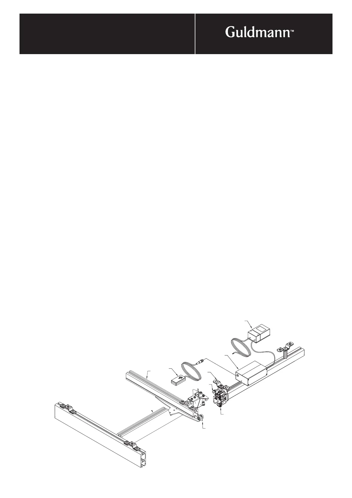
A. The transformer wires, 24V AC, are connected to the
PCB. Transformer: 110/240V AC - 24V AC.
B. Flexible installation of the Combi-lock is possible. The
safety lock for fixed rail is supplied with a tongue and
a standard threaded spindle of 600 mm (24") in length.
The length of the threaded spindle must be adapted to
the specific installation. A longer threaded spindle, up to
1000 mm (40") in length, can be mounted. This makes
it possible to install the safety lock for fixed rail and the
motor unit at a considerable distance from each other if
this is appropriate for the installation in question.
C. Safetylock for Combi-lock bracket is always supplied
with the safety lock for fixed rail and must always be
used together with a standard ceiling bracket or any
extended ceiling bracket.
D. Hand control
E. Ceiling bracket, use the bracket as a drill gauge. For
service and maintenance considerations it is best to use
at least 5 mm (
1
/
4
") spacers beneath both fittings for
permanent and parallel tracks above the Combi-Lock.
F. Mini rail.
G. Traverse Trolley.
H. The electronically activated Combi-Lock is equipped
with an electronic sensor.
The sensor is connected to the printed circuit board
with a terminal strip (brown/brown and blue/blue).
The leads are concealed in the cable tie.
The distance between sensors must be even with
track column width on 1-1.5 mm (
1
/
16
" –
3
/
16
"). Sensors
may not be positioned so close that they can collide.
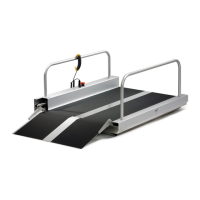
I. The traverse rail is a Maxi or a Jumbo rail which has
been reduced to the height of a Mini rail in the place
where the safety lock for the traverse rail is installed.