PSU Series User Manual
118
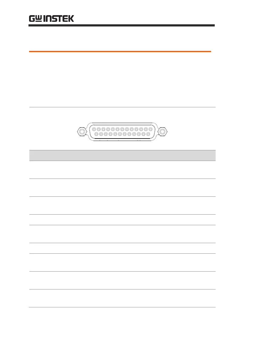
Analog Control Connector Overview
The Analog Control Connector is a 25 pin
connector that can be used with the ARC (analog
remote control) kit for wiring connections. The
connector is used for all analog remote control. The
pins used determine what remote control mode is
used.
This is the common line for the status signal pins 2
to 3 and 14 to 16.
This line is on when the PSU is in CV mode
(photocoupler open collector output)
1
.
This line is on when the PSU is in CC mode
(photocoupler open collector output)
1
.
Trigger signal input line (for test script only).
This is the common line for status signal pins 4
and 17.
Output shutdown control line. The output is
turned off when a low level TTL signal is applied.
Negative input line for master-slave parallel
operation.
Positive input line for master-slave parallel
operation.

 Loading...


