COMMUNICATION INTERFACE
161
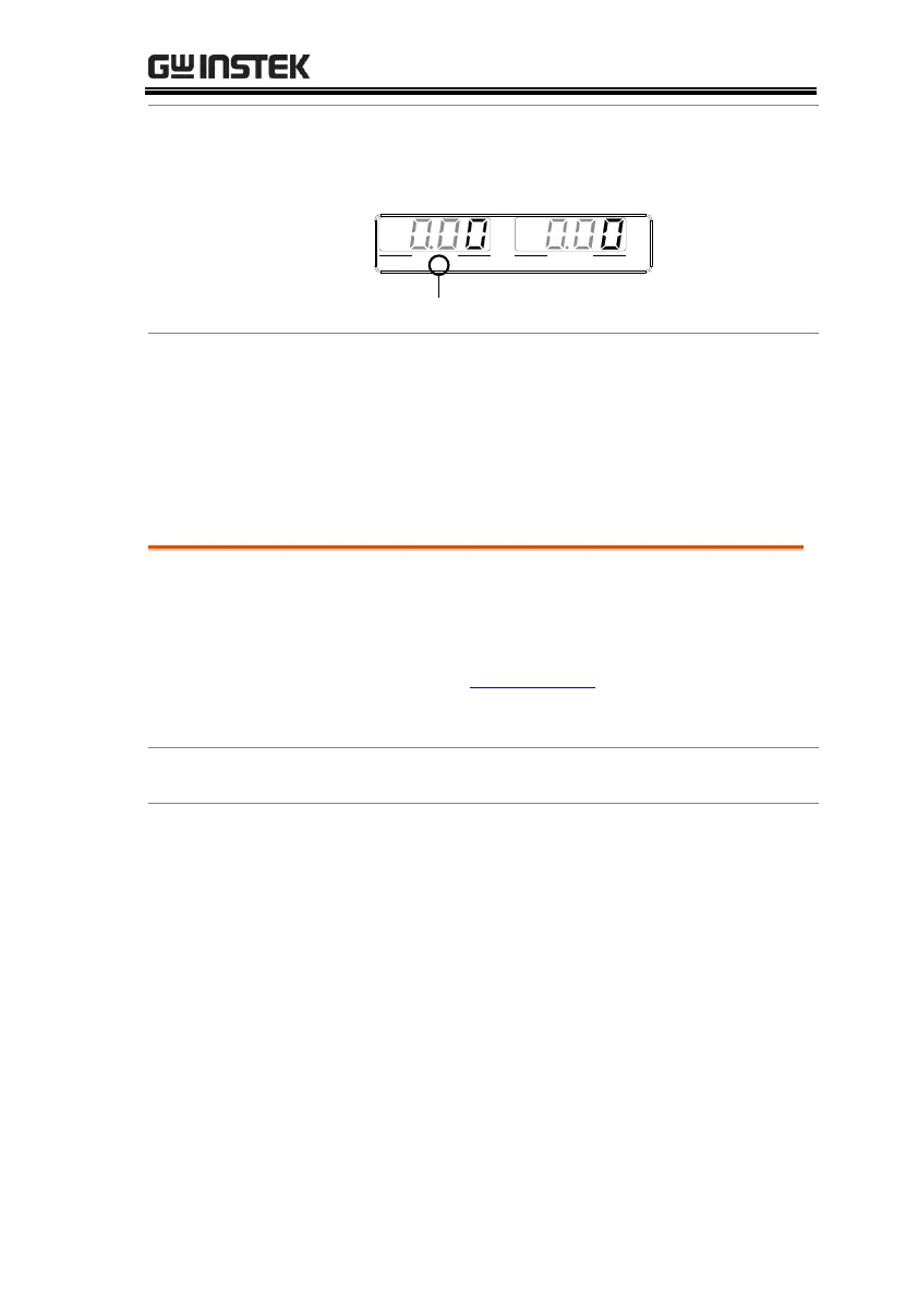
7. The RMT indicator will turn on when a remote
connection has been established.
RMT indicator
AV
VOLTAGE CURRENT
VSR LAN RMT ERR DLY ALM ISR M 1 M 2 M 3 RUN
C V C C
Maximum 15 devices altogether, 20m cable
length, 2m between each device
Unique address assigned to each device
At least 2/3 of the devices turned On
No loop or parallel connection
GPIB Function Check
To test the GPIB functionality, National
Instruments Measurement and Automation
Explorer can be used. This program is available on
the NI website, www.ni.com., via a search for the
VISA Run-time Engine page, or “downloads” at
the following URL, http://www.ni.com/visa/
Operating System: Windows XP, 7, 8
1. Start the NI Measurement and Automation
Explorer (MAX) program. Using Windows,
press:
Start>All Programs>National
Instruments>Measurement & Automation

 Loading...


