PSU Series User Manual
144
Isolated Analog Control Option Overview
The Isolated Analog Connectors are 8 pin sockets
that are optically isolated from the power supply,
allowing inputs with ground references that differ
to the power supply. The isolated options include
either an isolated voltage (0~5V/0~10V) interface
or an isolated current (4~20mA) interface. Only
one type of isolated interface can be used at any
one time. The pins used determine what remote
control mode is used.
The GPIB Option (PSU-GPIB), the isolated voltage
option (PSU-ISO-V) and the isolated current option
(PSU-ISO-I) all use the same option slot, meaning
that only one of the three options can be used at any
one time.
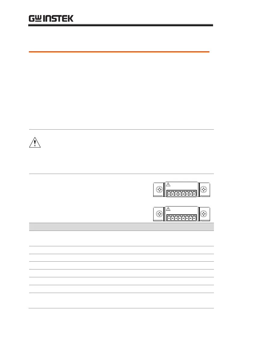
Isolated Voltage Connector
1 2 3 4 5 6 7 8
ISOLATED PROGRAMMING
0 – 5V / 0 – 10V
Isolated Current Connector
1 2 3 4 5 6 7 8
ISOLATED PROGRAMMING
4 – 20mA
Shield, connected internally to the chassis of the
power supply.
Output Voltage programming input.
Output Current programming input.
Ground for programming signals.
Ground for programming signals.
Output Voltage monitoring output.
Output Current monitoring output.
Shield, connected internally to the chassis of the
power supply.

 Loading...


