EasyManuals Logo

GW Instek PSU Series User Manual

GW Instek PSU Series
211 pages
To Next Page IconTo Next Page
To Previous Page IconTo Previous Page
Page #137 background imageLoading...
Page #137 background image
ANALOG CONTROL
137
External Operation and Status Monitoring
Background
The analog control connector can also be used to
monitor the status operation and alarm status of
the instrument.
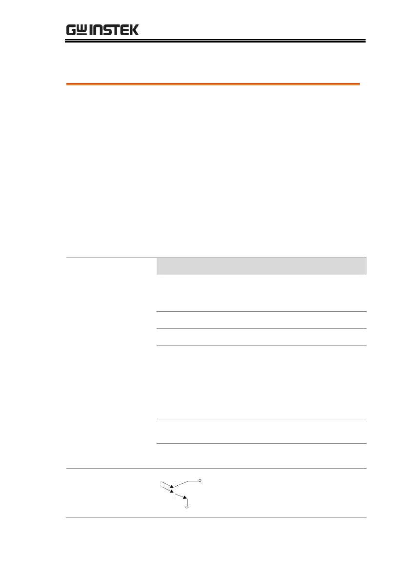
The pins are isolated from the power supply
internal circuitry by photo couplers. Status Com1
(Pin 1) and Status Com2 (Pin 5) are photo coupler
emitter outputs, whilst pins 2~3, 14~17 are photo
coupler collector outputs.
A maximum of 30V and 8mA can be applied to
each pin. The Status Com pin is floating with an
isolation voltage of 60V.
Pinout
Name and Pin
Description
STATUS
COM1
1
Common (photo coupler
emitter) for status signals 2, 3,
14, 15 and 16.
CV STATUS
2
Low when CV mode is active.
CC STATUS
3
Low when CC mode is active.
ALM
STATUS
14
Low when any of the
protection modes are tripped
(OVP, OCP, Sense_ALM,
OTP_M, AC Fail, OTP_S,
Fan_Fail, HW_OVP, and
Shutdown). Active low.
PWR ON
STATUS
15
Active low.
OUT ON
STATUS
16
Low when the output is on.
Schematic
Pins 2, 3, 14, 15, 16
1 (Status COM1)

Table of Contents

Other manuals for GW Instek PSU Series

Questions and Answers:

Question and Answer IconNeed help?

Do you have a question about the GW Instek PSU Series and is the answer not in the manual?

GW Instek PSU Series Specifications

General IconGeneral
BrandGW Instek
ModelPSU Series
CategoryPower Supply
LanguageEnglish

Related product manuals