ANALOG CONTROL
127
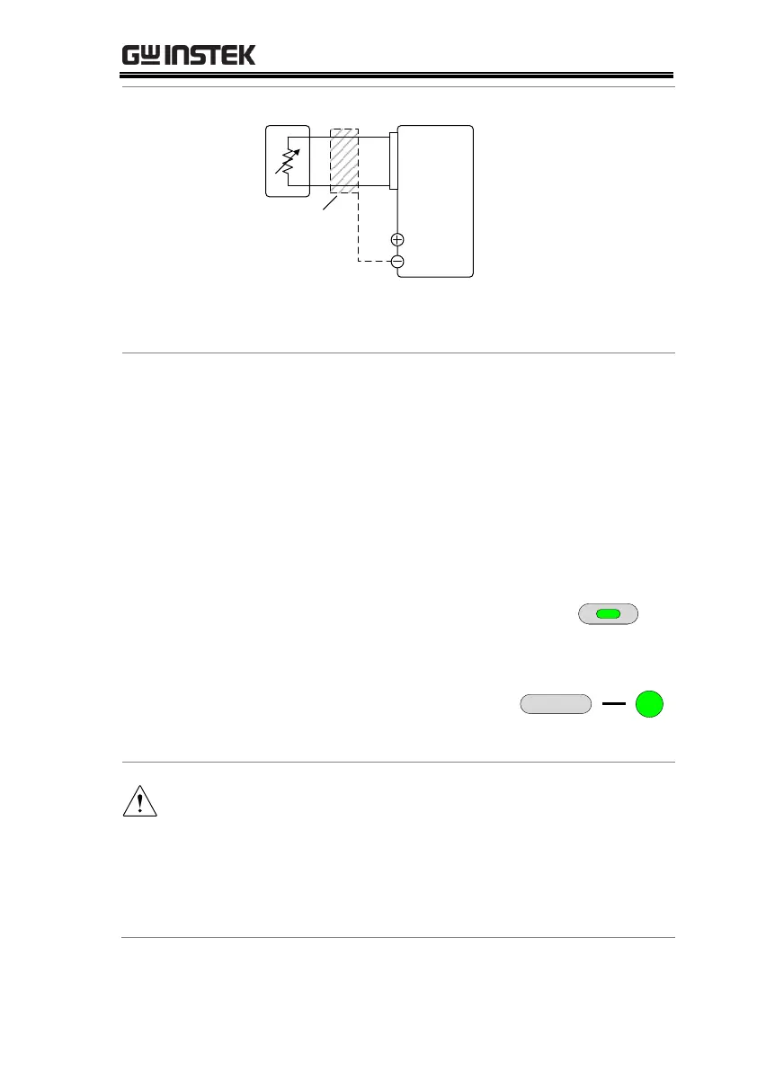
PSUEXT-R
Analog
connector
23
22
Output
Terminal
2 core shielded
wire or twisted
pair
Pin22 → EXT-R
Pin23 → EXT-R
Wire shield → negative (-) output terminal
1. Connect the external resistance according to the
connection diagrams above.
2. Set the F-90 (CV Control)
configuration settings to 2 for
Ext-R rising or 3 for Ext-R falling.
Be sure to cycle the power after the power on
configuration has been set.
3. Press the Function key and confirm
the new configuration settings
(F-90=2 or 3).
4. Press the Output key. The
voltage can now be
controlled with the External
resistance.
Ensure the resistor(s) and cables used exceed the
isolation voltage of the power supply. For example:
insulation tubes with a withstand voltage higher than
the power supply can be used.
When choosing an external resistor ensure the resistor
can withstand a high degree of heat.

 Loading...


