ANALOG CONTROL
129
The falling resistance configuration is recommended
for safety reasons. In the event that the cables become
accidentaly disconnected, the current output will drop
to zero (high Ω). Under similar circumstances using
the rising configuration, an unexpectedly high current
would be output.
If swtiches are used to switch between fixed
resistances, use switches that avoid creating open
circuits. Use short-circuit or continous resistance
switches.
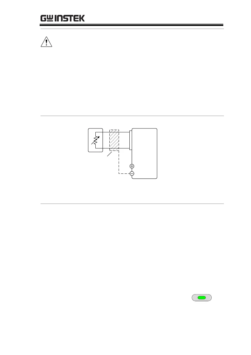
PSUEXT-R
Analog
connector
23
21
Output
Terminal
2 core shielded
wire or twisted
pair
Pin21 → EXT-R
Pin23 → EXT-R
Wire shield → negative (-) output terminal
1. Connect the external resistance according to the
connection diagrams above.
2. Set the F-91 (CC Control)
configuration settings to 2 for
external resistor rising or to 3 for
external resistor falling.
Be sure to cycle the power after the power on
configuration has been set.
3. Press the Function key and confirm
the new configuration settings
(F-91 = 2 or 3).

 Loading...


