PSU Series User Manual
132
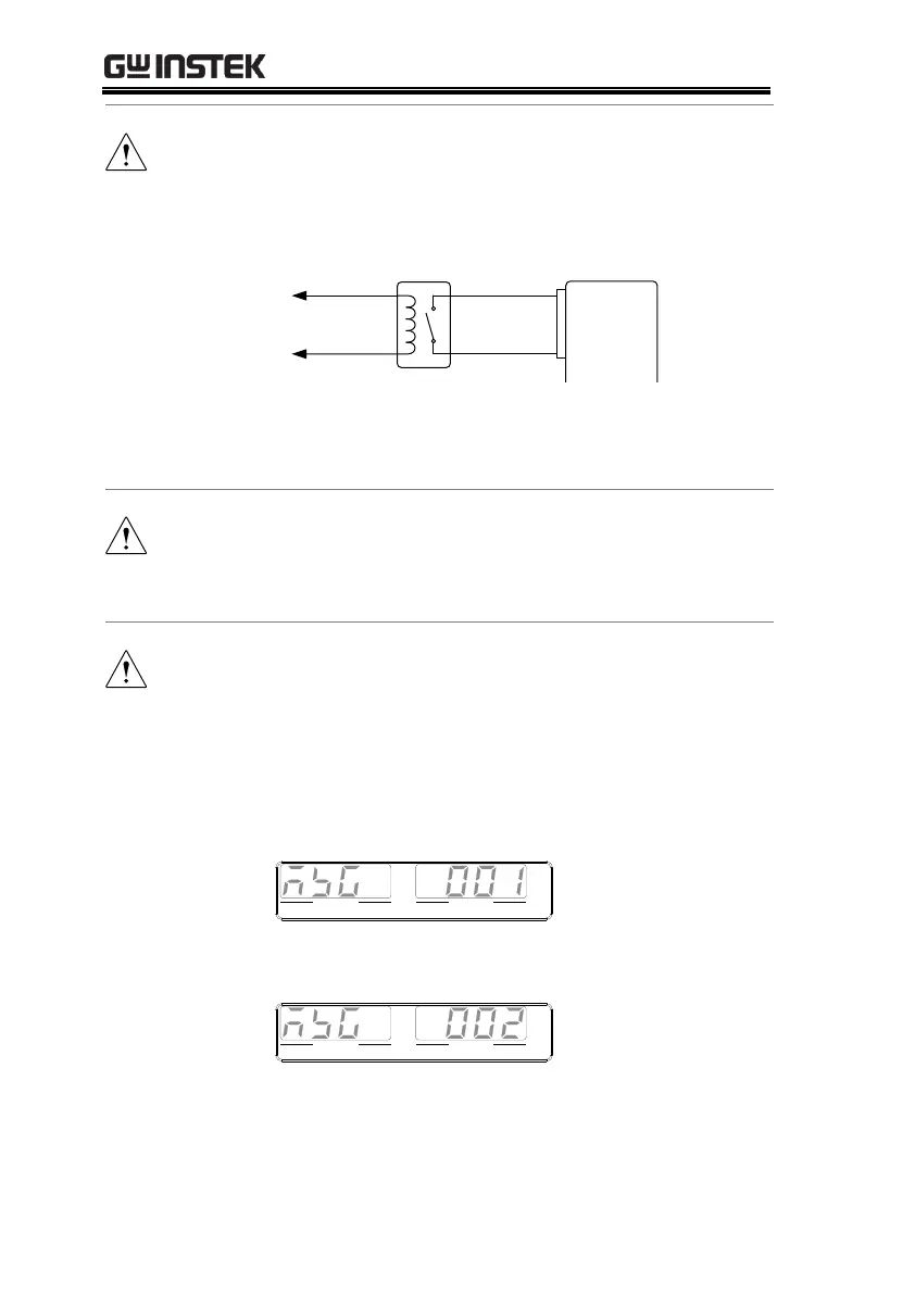
When using a switch over long distances, please use a
switch relay to extend the line from the coil side of the
relay.
Switch
Relay
Line
extension
Analog
connector
Output
Terminal
20
19
If a single switch control is to be used for multiple
units, please isolate each instrument. This can be
achieved by using a relay.
Ensure the cables used and the switch exceed the
isolation voltage of the power supply. For example:
insulation tubes with a withstand voltage higher than
the power supply can be used.
Messages: If F-94 = 0 (High = on) and pin 19 is low
(0) “MSG 001” will be displayed on the display.
If F-94 = 1 (Low = on) and pin 19 is high (1) “MSG
002” will be displayed on the display.
VOLTAGE CURRENT
VSR LAN RMT ERR DLY ALM ISR M 1 M 2 M 3 RUN
C V C C
V A
VOLTAGE CURRENT
VSR LAN RMT ERR DLY ALM ISR M 1 M 2 M 3 RUN
C V C C
V A

 Loading...


