COMMUNICATION INTERFACE
167
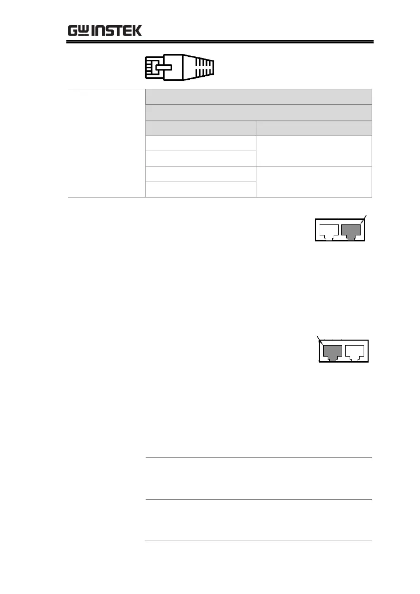
Diagram of End
terminal
connector
End terminal
connector from
PSU-232 or PSU-
485 connection
kit.
1. Connect the RS232 serial cable
(include in the PSU-232
connection kit) or RS485 serial
cable (include in the PSU-485
connection kit) to the Remote IN
port on the real panel.
Connect the other end of the cable
to the PC.
2. Connect the end terminal
connector (include in the PSU-232
or RS-485 connection kit) to the
Remote OUT port on the rear
panel.
3. Press the Function key to enter
the Normal configuration
settings.
Set the following UART settings:
Interface: 0= Disable UART,
1=RS232, 2=RS485 4W,
3=RS485 2W
Set the baud rate: 0=1200,
1=2400, 2=4800, 3=9600, 4=19200,
5=38400, 6=57600, 7=115200

 Loading...


