OPERATION
73
After the power supplies are connected in
parallel, if you want to use the analog connector
to control the power supplies, you must
disassemble the cable of the master and then
wire it yourself for control.
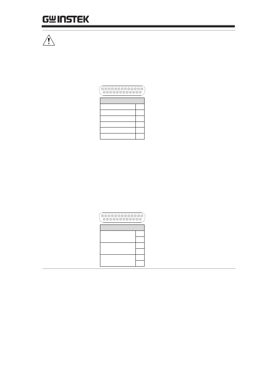
Pin signal diagram is as shown below.
22
23
21
23
19
20
EXT-V/R CV CONT
A COM
EXT-V/R CC CONT
A COM
OUT ON/OFF CONT
A COM
MASTER
The model of connecting in parallel has no place
voltage problem and can be used in common
ground.
The model of connecting in series has high
voltage due to the location. If analog control is
to be used, it cannot be used in common ground
and requires isolation control.
Pin signal diagram is as shown below.
22
23
21
23
19
20
Isolated Analog
0-10V
Isolated Analog
0-10V
NO relay driven
By 24V DO
MASTER
Parallel Output
Connection
If grounding the positive or negative terminals to the
reference ground, be sure to ground the appropriate
terminal on each unit (either positive or negative).

 Loading...


