Harness Installation Outline
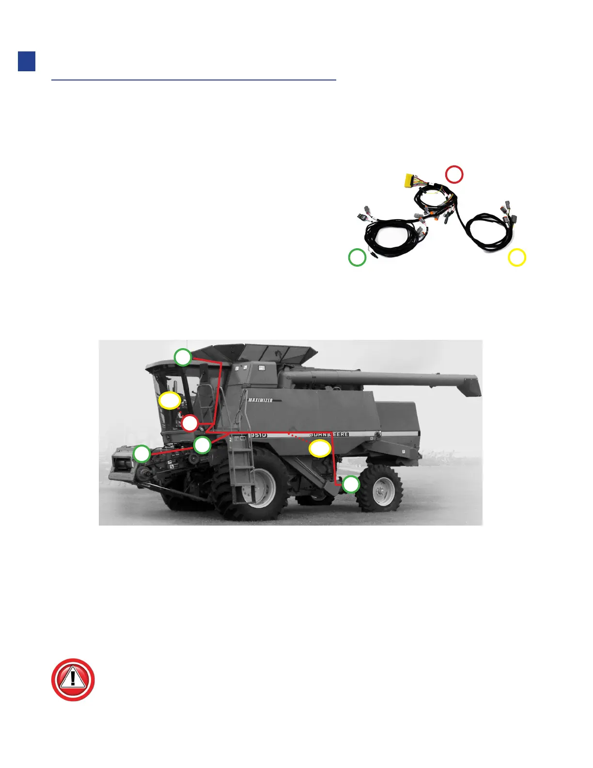
The main harness shown is the backbone of the Truesight system, which connects each
of the components to the controllers. The harness is divided into three main legs,
designated by numbers.
1. The “In-Cab” leg connects to:
•
Controllers
•
Power supply
•
Seat switch
2. The “Outside” leg connects to:
•
Crop sensor
•
Wheel angle sensor
•
Feeder position sensor
3. The “Steering Device” leg connects to:
•
Valve or motor which will steer the combine
• EZ-Steer or other cab mounted motors, this leg will remain in the cab
• For valve systems this will exit the cab with leg 2
Be careful to follow all steps except for installation procedures where instructions are
specific to machine.
1
2 3
D1
D2
A
B
C
E
F
A: In-cab components (leg 1)
B: Crop sensor (leg 2)
C: Wheel angle sensor (leg 2)
D1: Steering Wheel Motor connector In-cab (leg 3)
D2: Steering Valve connector (typical, may be mounted under cab (leg 3)
E: Feeder position sensor (leg 2)
F: Speed sensor (leg 2)
06
Installation