Table 2-1
2.2.2 Built-in PoE device rear panel introduction
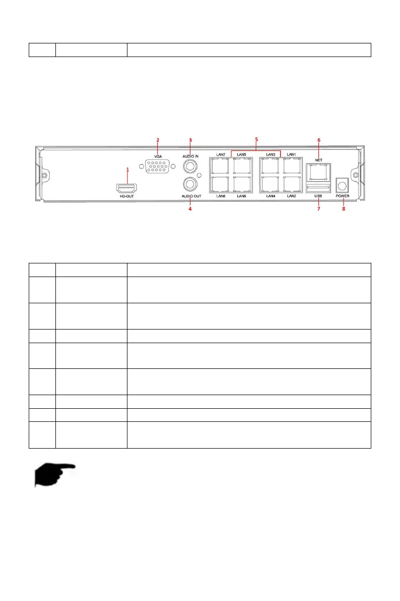
The schematic diagram of the rear panel of the built-in PoE device is as
follows:
Figure 2-3
The corresponding description of each interface in Figure 2-3 is shown in the
following table:
Connect HD display devices such as computer
monitors
Connect VGA display devices such as computer
monitors
Equipment audio input interface
Equipment audio output interface
Connect IP devices and power IP devices and
networks
Connect the mouse, U disk or removable hard disk
NOTE
The panel diagram does not reflect the product size and ratio. Please
refer to the actual product for details.
2.3 Mouse NOTEs