Destination DeviceSource DeviceHardware
Enclosure3: IOMB, B1Enclosure2: IOMB, B3
Table 48: Four Enclosures: One Host with a Single HBA
Destination DeviceSource DeviceHardware
Enclosure1: IOMA, A1Host1: P1Host Connections
Enclosure3: IOMB, B3Host1: P2
Enclosure2: IOMA, A1Enclosure1: IOMA, A3Enclosure Connections
Enclosure2: IOMB, B1Enclosure1: IOMB, B3
Enclosure3: IOMA, A1Enclosure2: IOMA, A3
Enclosure3: IOMB, B1Enclosure2: IOMB, B3
Enclosure4: IOMA, A1Enclosure3: IOMA, A3
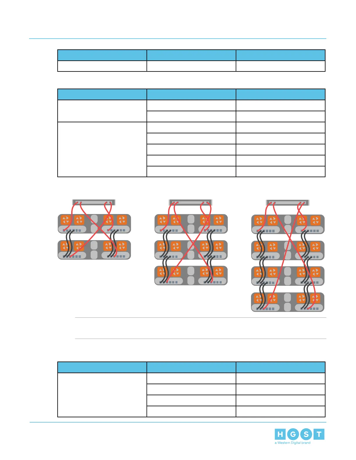
Figure 203: Enclosure Configurations with One Host with Two HBAs
Note: The diagram displays red SAS cables to indicate passive connections between the host and
the enclosure. The black SAS cables indicate active connections between each enclosure.
Table 49: Two Enclosures: One Host with Two HBAs
Destination DeviceSource DeviceHardware
Enclosure1: IOMA, A1Host1: P1Host Connections
Enclosure2: IOMB, B3Host1: P2
Enclosure1: IOMB, B1Host1: P3
Enclosure2: IOMA, A3Host1: P4
192
5 System Management
User Guide 5.4 Daisy Chaining

 Loading...