1. Place both CMAs into service position.
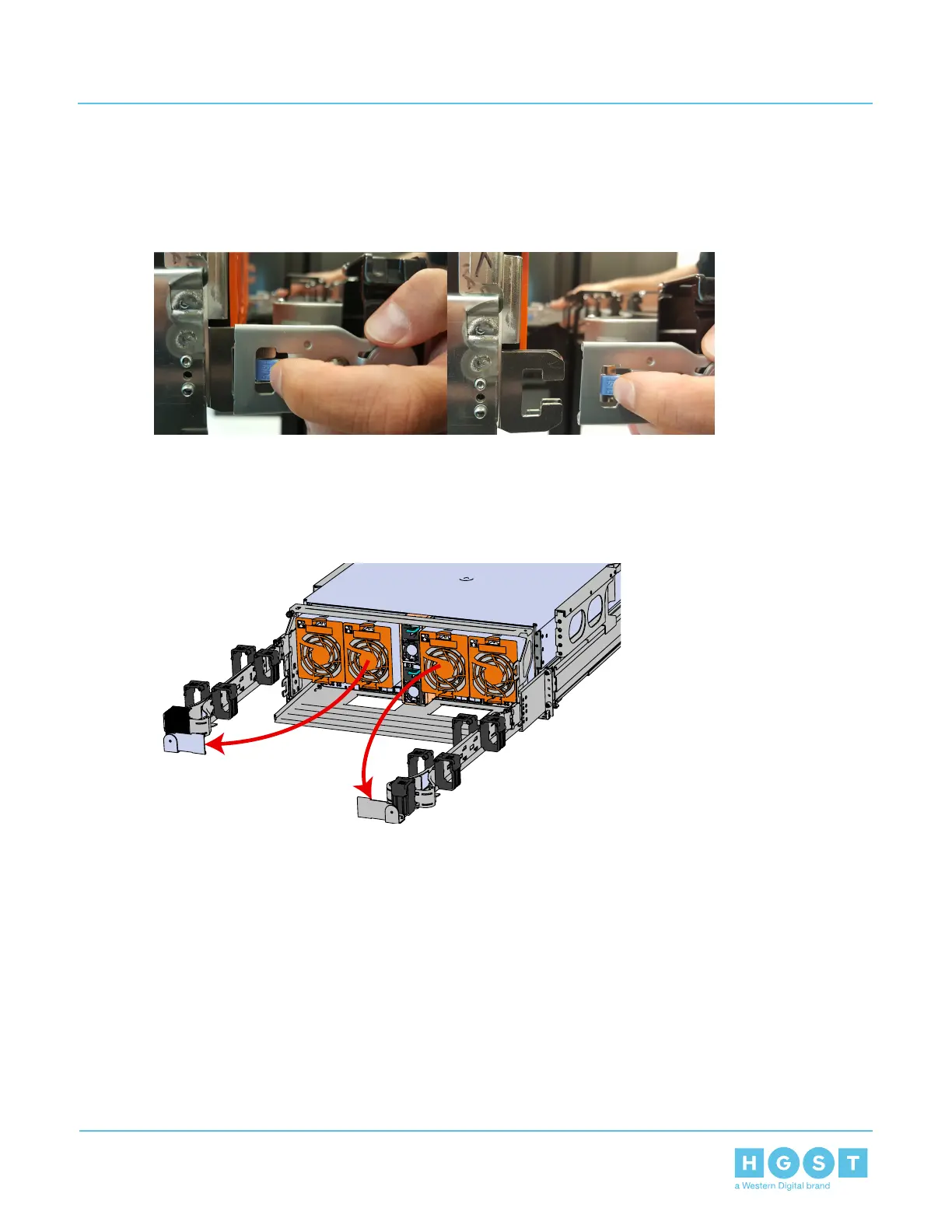
a) Unlatch the upper CMA at the elbow connector by pressing the blue release button to unlatch the
connector from the rail.
Figure 76: Unlatching a CMA Connector
b) Swing the CMA away from the enclosure.
c) Do the same for the lower CMA arm as what was done for the upper.
d) Both arms should be extended away from the enclosure as shown in the following example.
Figure 77: CMAs in service position (Cables not shown)
2. Power down the Enclosure.
a) Locate the redundant PSUs at the rear of the enclosure.
82
4 Part Replacement
User Guide 4.8 Rails Replacement

 Loading...