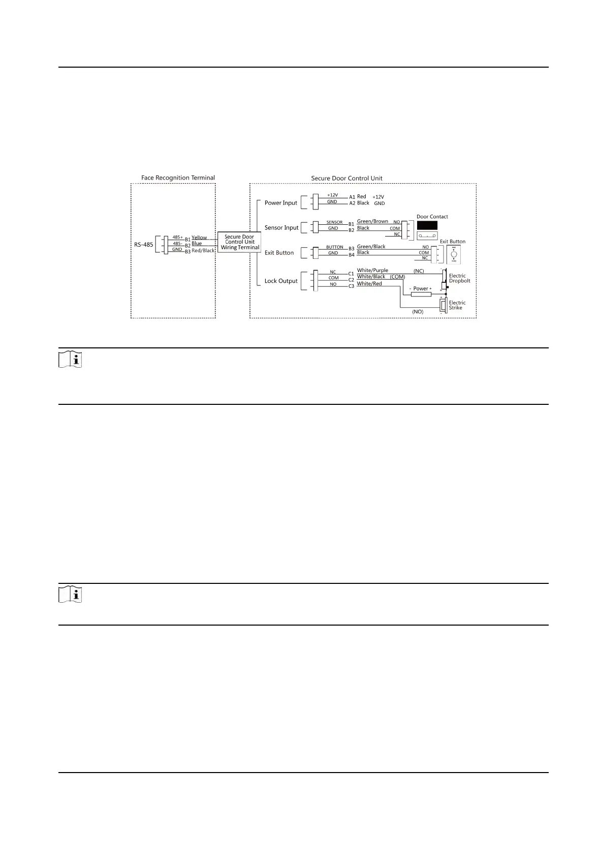
4.3 Wire Secure Door Control Unit
You can connect the terminal with the secure door control unit.
The wiring diagram is as follows.
Figure 4-2 Secure Door Control Unit Wiring
Note
The secure door control unit should connect to an external power supply separately. The suggested
e
xternal power supply is 12V, 0.5A.
4.4 Wire Fire Module
4.4.1 Wiring Diagram of Door Open When Powering O
Lock Type: Anode Lock,
Magnec Lock, and Electric Bolt (NO)
Security Type: Door Open When Powering O
Scenario: Installed in Fire Engine Access
Type 1
Note
The
re system controls the power supply of the access control system.
DS-K1T341A Series Face Recognion Terminal User Manual
13

 Loading...