128
_____________________________________________________________________________________________
5.3 Testing an Element in a Circuit
______________________________________________________________________________________________
R4R3
R2R1
HL
R4R3
R2R1
HL
Guard terminal
NOTE
Two resistors in parallel
Coil and capacitor in parallel
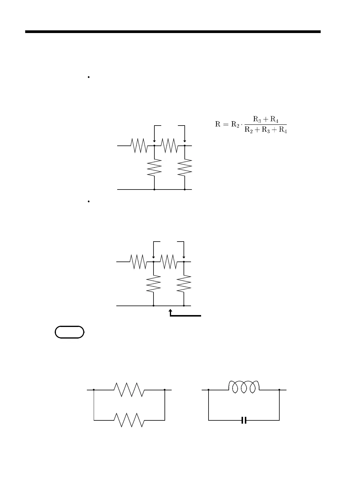
5.3 Testing an Element in a Circuit
Testing an element in a circuit is not possible without guarding.
Referring to the following figure, when measuring a resistance value for the
resistor R
2
, even if the tips of the two probes are contacted against the ends
of the resistor R
2
, considering the sum of the current flowing through the
resistor R
2
and the current flowing through the resistors R
3
and R
4
, what is
obtained is the resistance value for the parallel combination:
If as shown in the next figure a guard terminal is used, the current flowing
through the resistors R
3
(not flowing through R
4
) is absorbed by this guard
terminal, so that the resistance value for the resistor R
2
is accurately
measured.
The accuracy of measurement will not be improved in cases where for
example
R
2
>> R
3
and R
3
is close to zero.
As shown in the figure below, it is not possible to use this type of separation
process for testing of the impedance values of two resistors or other elements
of identical types which are connected in parallel, or for testing of the
impedance values of a coil and a capacitor which are connected in parallel.
 Loading...


