36
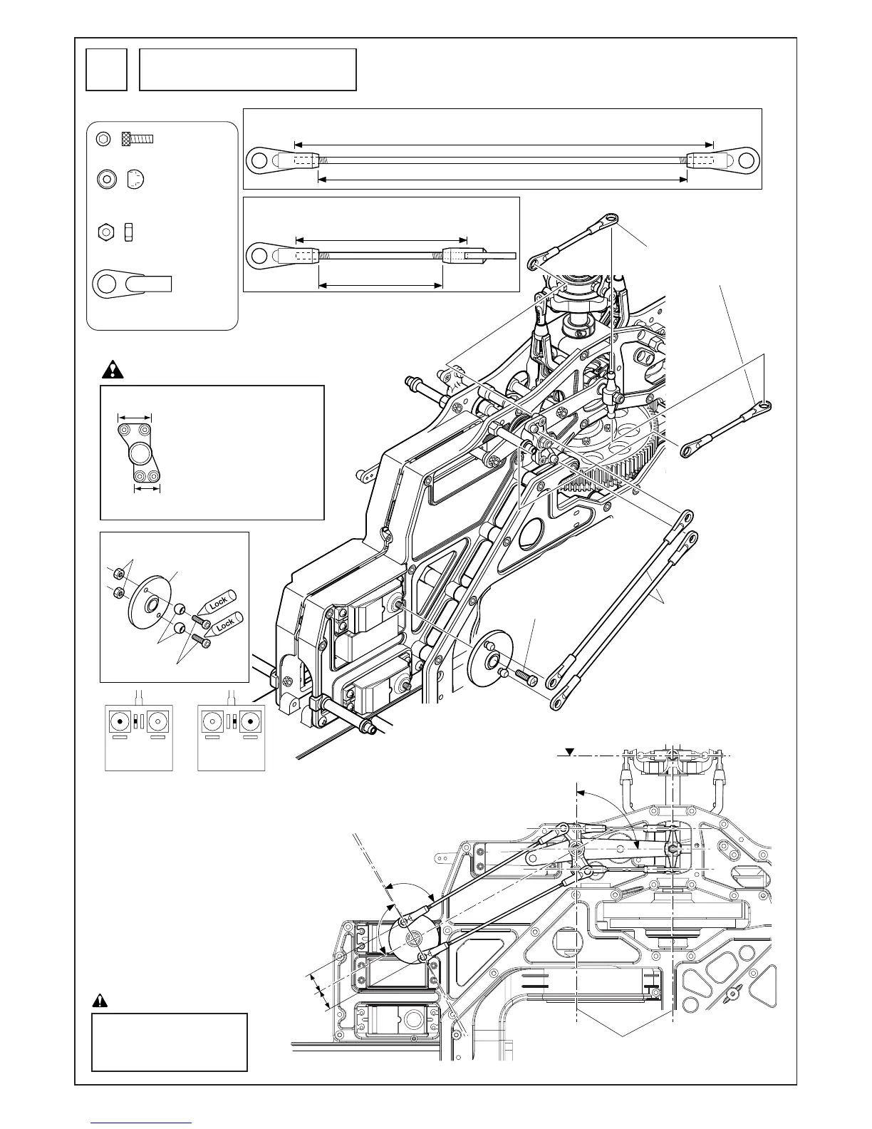
X型レバー
/エレベータートルクレバーロッド
X-type lever rod/elevator torque
lever rod (2 rods)
サーボに付属のネジ
Screws included with servo
エレベーターロッド
Elevator rod
90˚
90
˚
90
˚
約10mm
Approx.
10mm
モード I
Mode I
モード II
Mode II
送信機のスティックの 位 置
Position of the transmitter stick.
水平
Horizontal
平行
Parallel
A
B
広い
Wide
狭い
Narrow
エレベーターロッド(2セット)
Elevator rod (2 rods)
X型レバー/ エレベータートルクレバーロッド(2セット)
X-type lever rod/elevator torque lever rod (2 rods)
サーボホーン
Servo horn
M2ナット
M2 nut
EX ø5ボール
EX ø5 ball
M2X6CS
110mm
約97mm Approx. 97mm
L
45mm
約32.5mm
Approx. 32.5 mm
エレベーターのリンケージ
Elevator linkage
34
AとBの長さはサーボによっ
て異なります。
The length of the rods A and
B vary depending on servo.
送信機のスティックがニュートラルでトリムが
ニュートラルの時、右の図のようにX型レバー
とサーボホーンが 90°になるようにし、A の
ロッドの長さを調整後、Bのロッド長さを調整
してください。
Make sure TX elevator stick and trim is centered.
Adjust the length of rod A first then adjust the length of
rod B so the X lever and elevator torque pivot are at
right angles to each other as illustrated. Lengths give
above are starting points. Lengths vary with
servos used. If lengths of rod A and rod B end up
different, servo is not centered to X lever travel. Start
again, making each rod same length to the centerline of
the servo horn screw as illustrated on the right, and
relocate EX servo horn balls accordingly.
X 型レバーは広い方が上になる
よう取付けてください。
Install the X-type lever with the wide
end up.
M2X6CS............................... 2
EX ø5ボール ........................ 2
EX ø5 ball
M2ナット............................. 2
M2 nut
M2ロッドエンド................. 8
M2 rod end
注意Caution
スワッシュプレートが水平の時、X
型レバー(L)とエレベータートルクレ
バーが平行になるよう、エレベー
ターロッドでつなぎます。
Connect the linkages to the X-type lever
(L) and elevator torque lever making sure
the rods are parallel and equal length
when the swash plate is level and
horizontal.
注意 Caution