38
サーボに付属のネジ
Screw included with the servo
機首方向
Towards the nose of the unit.
モードI
Mode I
モードII
Mode II
送信機のスティックの 位 置
Position of the transmitter stick.
サーボホーンAssy
Servo horn assembly
水平
Horizontal
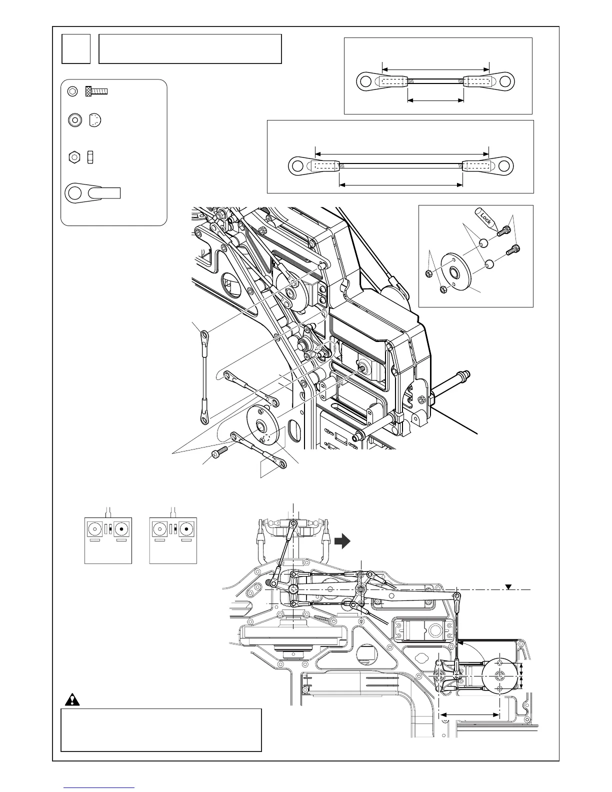
65mm
約46mm Approx. 46mm
40mm
コレクティブピッチレバー/
T型レバーロッド
Collective pitch lever/
T-type lever rod
コレクティブピッチロッド
Collective pitch rod
コレクティブピッチレバー/T型レバーロッド
Collective pitch lever/T-type lever rod
コレクティブピッチロッド(2セット)
Collective pitch rod (2 rods)
約21mm
Approx. 21mm
M2ナット
M2 nut
サーボホーン
Servo horn
M2X6CS
EX ø5ボール
EX ø5 ball
12.5mm
12.5mm
平行
Parallel
コレクティブピッチのリンケージ
Collective pitch linkage
36
M2X6CS............................... 2
EX ø5ボール ........................ 2
EX ø5 ball
M2ナット............................. 2
M2 nut
M2ロッドエンド................. 6
M2 rod end
送信機のスティックがニュートラルで、
トリムがニュートラルの時、右図のよう
になるようにコレクティブピッチを調整
してください。
Adjust collective pitch lever/T-type lever rod
so collective lever is horizontally level per right
illustration. Make sure pitch trim is centered
and/or inhibited and TX throttle/collective stick
is centered per above illustration.
送信機のピッチカーブ設定が50%の位置のときの図です。
Illustration at right shows servo position at a 50%
middle point radio pitch curve setting, all activated
flight modes.
注意 Caution