Copyright © 2019, 2021, Hitachi, Ltd.
DKC910IHitachi Proprietary
[INST(IN)09-01-110]
Rev.0.5
INST(IN)09-01-110
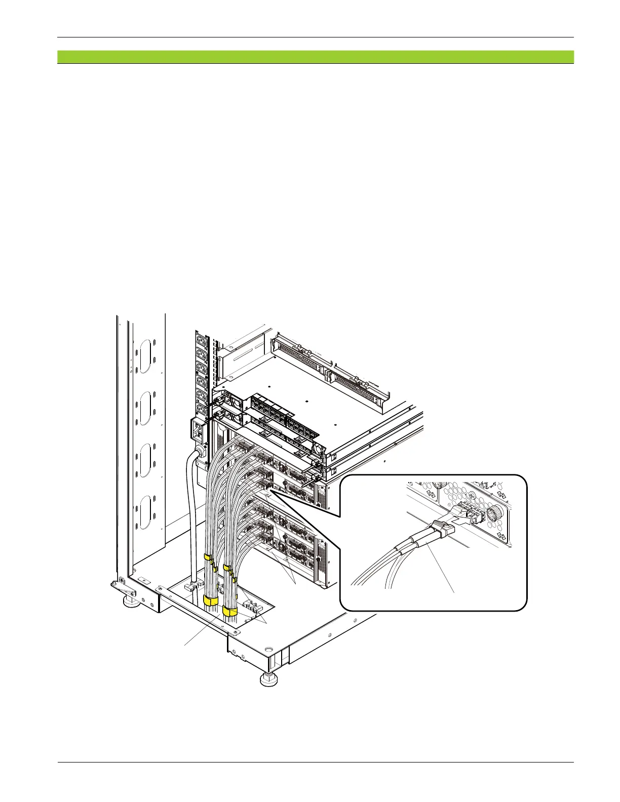
2. Pull all the iSCSI cables into the rack frame passing them through an opening for cables on the bottom
plate of the rack frame.
3. Connect the iSCSI cable to the connector of the each port.
NOTE : • Insert the iSCSI cables until they are xed to the Small Form-Factor Pluggable (SFP).
If the iSCSI cables are inserted half in the Small Form-Factor Pluggable (SFP), the
Controller Board continues to detect the iSCSI cable failures, and the I/O processing
of the Controller Board may be deteriorated.
• The location of iSCSI cable connectors is different depending on Controller Board.
Check the location before connecting a cable.
• Check that optional cable latch clicks and the cables are surely connected.
4. Fix the iSCSI cables with binders giving them excessive lengths.
If the length of the iSCSI cables is too long, put the extra cable length outside the rack.
Figure 9-9 iSCSI Cable Routing
Cable passing opening
iSCSI Interface cables (Optic)
DKC
Rear view of Rack Frame
Binder