Copyright © 2019, 2021, Hitachi, Ltd.
DKC910IHitachi Proprietary
[INST(IN)03-01-110]
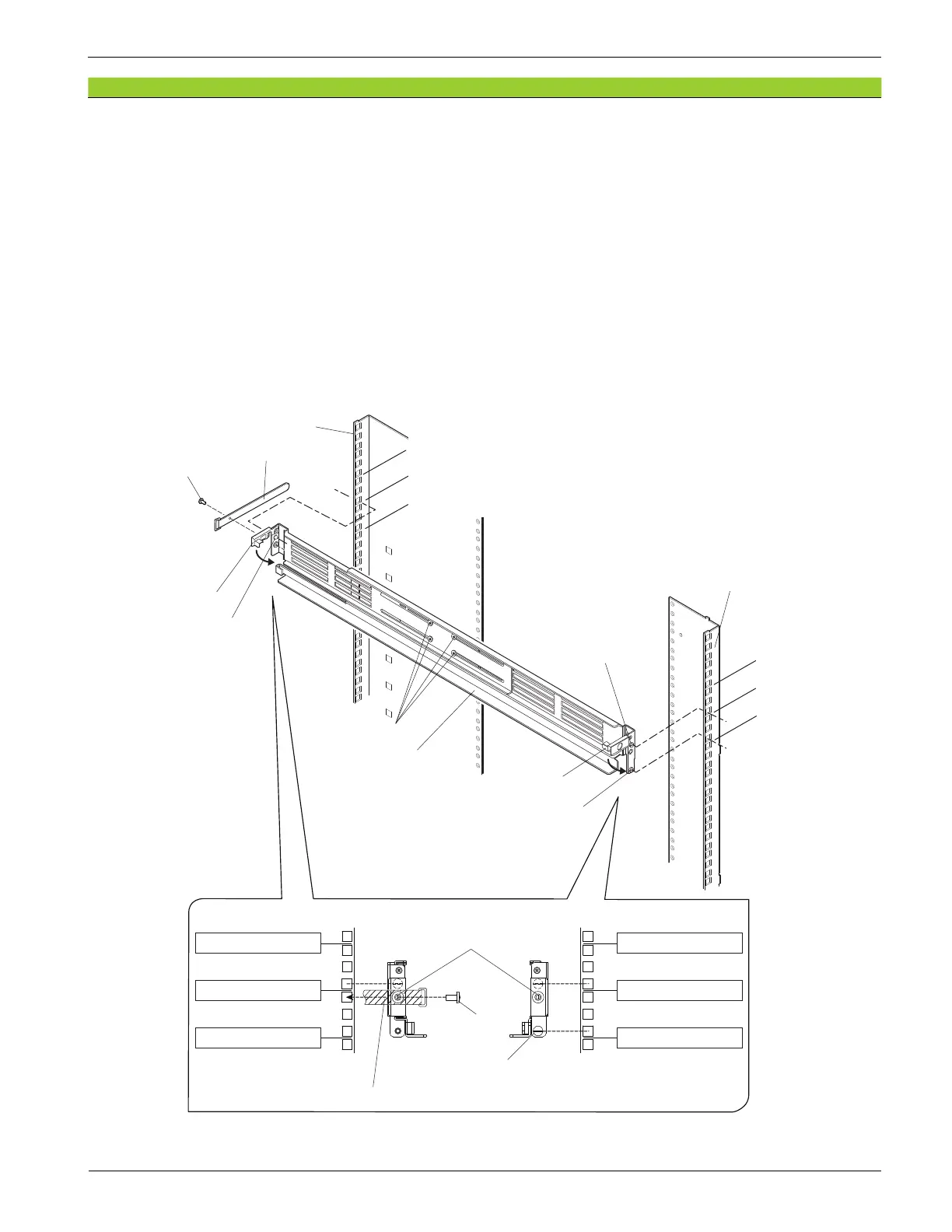
(3) Loosen the four screws on the side of the rail (R) and adjust the rail (R) length.
When the rack frame and the rail width do not match even if loosening the screws, remove the four
screws, adjust the length, and then x the rail with four screws again.
(4) Fit the positioning pins (at three places in front and rear) in the holes in the position to be installed
on the right side of the rack.
(5) Close the clips on the rail (R) and install the rail (R) in the rack.
(6) Tighten the four screws on the side of the rail (R).
(7) Fix the rear side of rail (R) with screw and loop cable tie. The xing position is the third hole from
the bottom of the unit boundary line.
(8) Install a rail (L) on the left side of the rack in the similar procedure.
Figure 3-11 Installing Rails
*1: Lowest unit of installing position Unit
Frame (Rear view)
Positioning pin
Rail (R)
1 Unit
1 Unit
1 Unit
1 Unit
Clip
Clip
Positioning pin
Frame (Front view)
Positioning pin
Four screws
Screw
Unit boundary
Unit boundary
Unit boundary
1 Unit
1 Unit (*1)
Rear
Positioning pin
Screw
Positioning pin
Unit boundary
Unit boundary
Unit boundary
1 Unit
1 Unit (*1)
Front
Loop cable tie
Loop cable tie
Rev.2
INST(IN)03-01-110