Copyright © 2019, 2021, Hitachi, Ltd.
DKC910IHitachi Proprietary
[INST(IN)07-04-30]
Rev.2
INST(IN)07-04-30
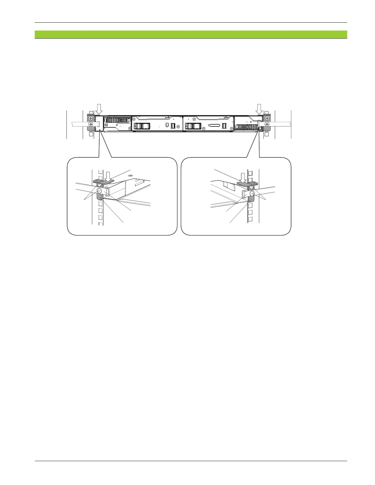
(4) Fix the stopper (L) with the two binding screws while pressing it downward.
(5) Fix the stopper (R) with the two binding screws while pressing it downward.
Figure 7-16 Fixing Stoppers
(6) Check that the top surface of the Controller Chassis is t on the stopper (L) and the stopper (R)
without gaps.
(The stoppers might be rotated and raised by tightening the binding screws.)
NOTE: When the installation of the stoppers is difficult because the space between the
Controller Chassis and the Chassis above it is too narrow, contact the Technical
Support Division to resolve the problem.
Stopper (L)
Rear view of rack
Stopper (R)
Binding
screws
Pressing the stopper downward
Binding
screws
Pressing the stopper downward
Pressing the stopper
downward
Pressing the stopper
downward
Loop cable tie
Loop cable tie