ABOUT THE SYSTEM SYSTEM FRONT VIEW
1-8
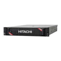
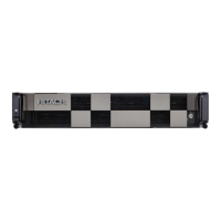
System Front View
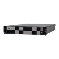
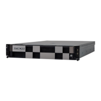
2.5” Storage Drive System
Figure 1-2. Front View
3 Server handle
Two server handles used for pulling the system out of the rack
THE HANDLES ARE DESIGNED FOR THE EXTENSION OF THE SYSTEM FROM THE RACK. THE
H
ANDLES ARE NOT DESIGNED TO CARRY THE WEIGHT OF THE SYSTEM. DO NOT USE THE
HANDLES TO MOVE OR LIFT THE SYSTEM.
4 Front control panel
Features power button with LED, ID button with LED and USB port.
See Front Control Panel and LEDs on page 1-11 for further information
5 Chassis
2U System chassis
444mm/17.5"(W)x 87.5mm/3.4"(H)x 866mm/34.1"(D)
6MB sled
There are two types for MB sled:
General SKU
GPU SKU
7 Fan modules Five 60 mm (2.36”) x 56 mm (2.20”) variable-speed dual-rotor fans
8 Fan assembly cover Open to service fan modules
Table 3: System Front View
NO FEATURE DESCRIPTION
1
2.5” Storage Drive
SATA/SAS HDD/SSD 0~3* or NVMe SSD 0~3 (CPU0) storage drive bay
2 SATA/SAS HDD/SSD 4~7* or NVMe SSD 4~7 (CPU1) storage drive bay
3 SATA/SAS HDD/SSD 8~11* or NVMe SSD 8~11 (CPU2) storage drive bay
4 SATA/SAS HDD/SSD 12~15** or NVMe SSD 12~15 (CPU3) storage drive bay
5 Front control panel Includes power/ID button, power/ID/status LED, and USB port
Table 2: System Component Overview (Continued)
NO.ITEM DESCRIPTION
❽
❶❷
❼❻
❸ ❹
❺
0
1
2
3
4 5 6 7 8 9 10 1112 13 1415
1
0
 Loading...
