INSTALLING THE HARDWARE PROCESSOR
2-34
2.11 Processor
All the instructions and images in this section are for illustration purposes only and may
not reflect the actual product.
Before attempting to service any component, make sure you are properly grounded and
wear ESD gloves to avoid damaging the components.
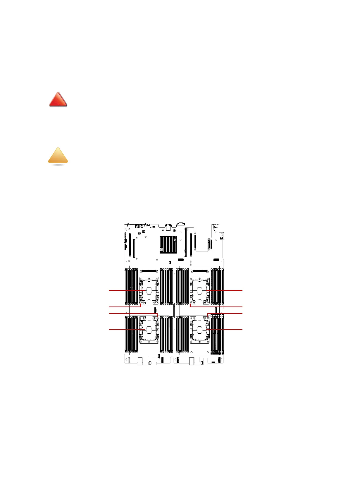
Processor Mapping
The following illustration provides a reference for the system's CPU location.
Figure 2-40. Processor Mapping
ENSURE ALL POWER IS DISCONNECTED FROM THE SYSTEM BEFORE PROCEEDING.
The use of ESD gloves is highly recommended when installing the processor and heat sink
assembly to prevent oxidation or inadvertently placing particulates on the LAND GRID ARRAY
(LGA).
CPU3CPU0
CPU2CPU1
CPU Pin1 Indicator
CPU Pin1 Indicator
CPU Pin1 Indicator
CPU Pin1 Indicator