4-10
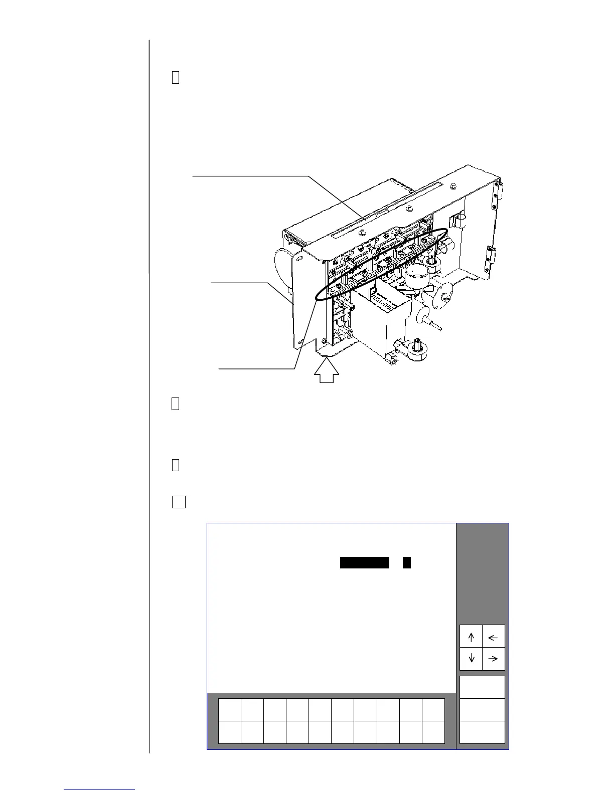
7 Remove the fixing screws (8 positions) at the upper and lower
connecting parts of the circulation unit. The pump unit can be removed.
"Caution 1": When removing the screws with a screwdriver, hold the
lower side of the unit door so that the unit door and hinge
may not be deformed.
"Caution 2": Put wiping paper under the pump unit to provide for an ink
drip.
8 Clean the portion stained with ink and make sure that the O-rings (4
positions) are securely mounted in the concave parts of the lower-side
circulation unit. Then, install a pump unit by reversing the above
procedure.
9 Perform “Ink refill” and adjust the pressure. Make sure that there is no
ink leak.
10 Reset the pump time to "0" on the “Parts usage time management”
screen.
Incre-
ment
Decre-
ment
Cancel
changes
Reset
Back
0 9 8 7 6 5 4 3 2 1
Status: XXXXXXXXXXX
2005.07.07 12:45 Parts usage time
Ink filter [ 0 0 0 0 0 ]
Circulation f. [ 0 0 0 0 0 ]
Makeup ink f. [ 0 0 0 0 0 ]
Air filter [ 0 0 0 0 0 ]
Pump [ 0 0 0 0 0 ]
Recovery filter [ 0 0 0 0 0 ]
Heating unit [ 0 0 0 0 0 ]
MV1 [ 0 0 0 0 0 ]
(hours)
MV2 [ 0 0 0 0 0 ]
MV3 [ 0 0 0 0 0 ]
MV4 [ 0 0 0 0 0 ]
MV5 [ 0 0 0 0 0 ]
MV6 [ 0 0 0 0 0 ]
MV7 [ 0 0 0 0 0 ]
MV8 [ 0 0 0 0 0 ]
MV9 [ 0 0 0 0 0 ]
(hours)
Update log 2005.07.07 12:45
<Consumption>
Ink [ 0 0 0 0 0 0 ] (ml)
Makeup ink [ 0 0 0 0 0 0 ] (ml)
Print count 0 0 0 0 0 0 0 0 0
Insert the screwdriver
from this slit.
Fixing screw
(8 positions)
Unit door
Hold this portion.
*) This figure is for the
PXR-D. The main ink tank
is not attached for the
PXR-P.

 Loading...