4-1
4. Maintenance of Circulation System (PXR-D, PXR-H)
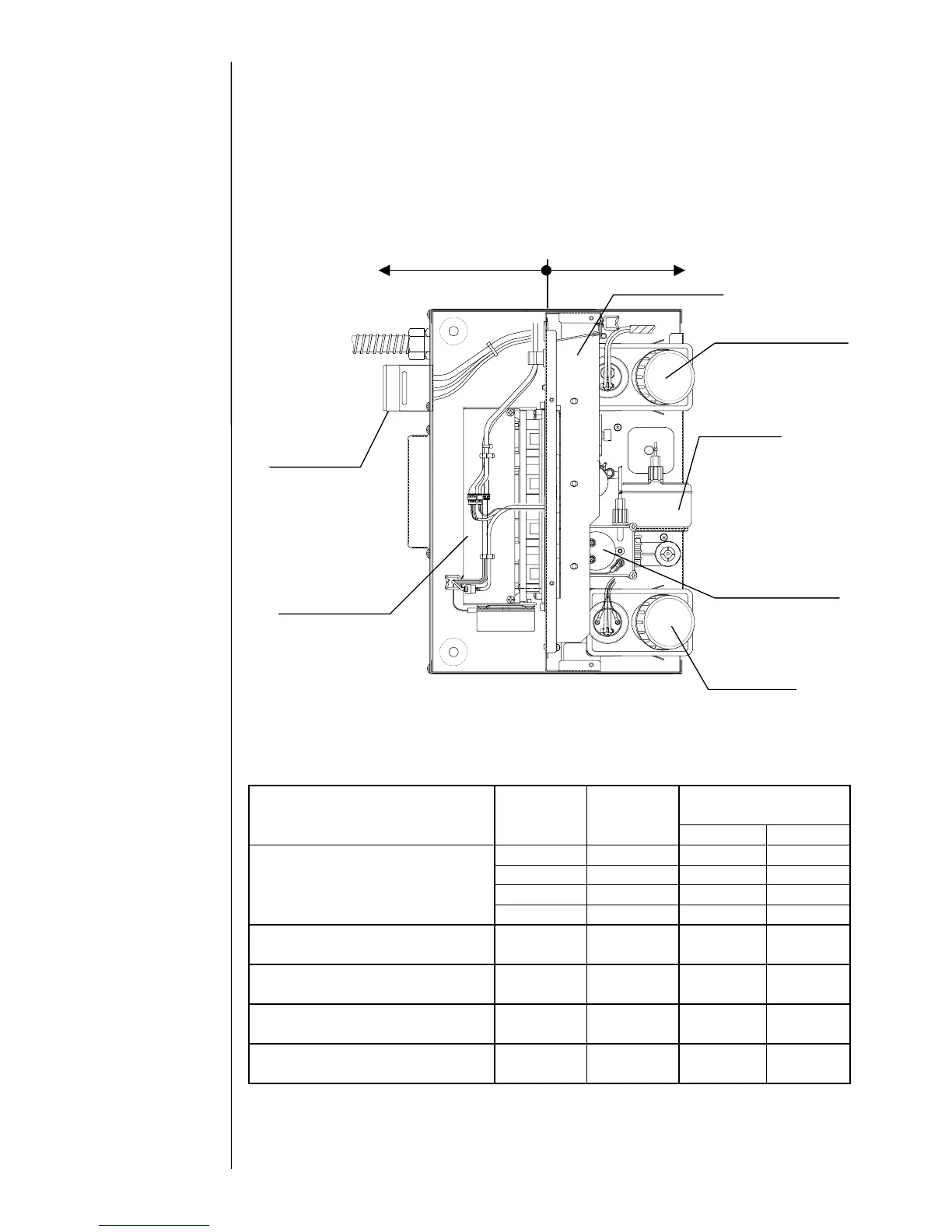
4.1 General Structure of Circulation System
4.1.1 The general structure of the circulation system is shown in the following
figure. Using an open/close type door (unit door) as a partition, the
system is roughly divided into an ink circulating area (the front side of the
equipment) and a driving part area (the rear side of the equipment).
Caution:
Since the circulation unit is made of plastic, tightening the screws with excessive
torque will break the unit. See the table below for reference torques:
Reference tightening
torque
Part name (used location)
Companion
parts name
Companion
material
N·m kgf·cm
ICU base A PBT(G30) 1.7±0.3 17.3±3
ICU base B PBT(G30) 1.7±0.3 17.3±3
Front panel PP 1.33±0.22 13.6±2.2
Self-tapping screw M4X12
(attaching pressure system, etc.)
Main ink tank
PP 1.33±0.22 13.6±2.2
Self-tapping screw M4X16
(attaching solenoid valve)
ICU base B PBT(G30) 1.7±0.3 17.3±3
Self-tapping screw M4X12
(attaching pump cover)
P side plate
ADC12
(aluminum)
1.7±0.3 17.3±3
Self-tapping screw B M3X10
(attaching ICU joint)
ICU base A PBT(G30) 0.5±0.1 5.1±1
Self-tapping screw 3X8
(attaching door lock body)
Door lock
body
POM 0.75 - 1.04 7.6 - 10.6
Makeup ink reservoi