4-24
5 Remove the removed tube from the fixing clamp.
6 Perform “4.1.3 Approach to the parts on the rear side of the equipment”
and open the unit door.
7 Remove the wires removed in 3 from the fixing clamps.
8 Pull out the tube removed in 4 from the rear side of the equipment.
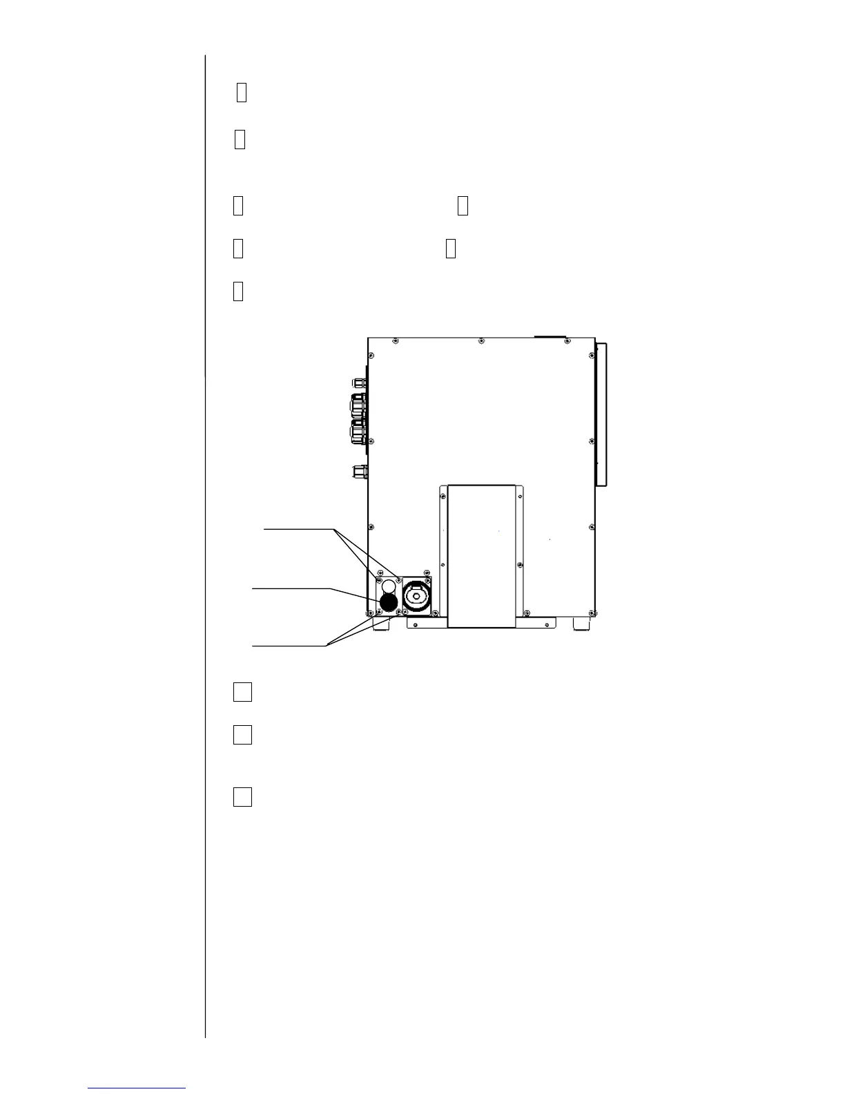
9 Remove the fixing screws (4 positions) of the print head on the rear side
of the equipment. The print head can be removed from the equipment.
10 Install a new print head by reversing the above procedure.
11 Perform “Ink Replenishment” and adjust the pressure.
Make sure that there is no ink leak.
12 Perform “Excitation adjustment” and “Auto-phase gain adjustment”.
Fixing screw
Fixing screw
Print head

 Loading...