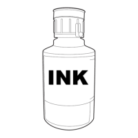
djust./oper. checkout
Proc. status:
XXXXXXXXX XXXXXXXXX
XXXXXXXXX XXXXXXXXX
XXXXXXXXX XXXXXXXXX
Auto-phase gain
adjustment
XXXXXXXXX
XXXXXXXXX
0 9 8 7 6 5 4 3 2 1
3 After the completion of the automatic adjustment, when the Back key
is pressed, the auto phase detection voltage is output and therefore,
confirm the waveform by an oscilloscope.
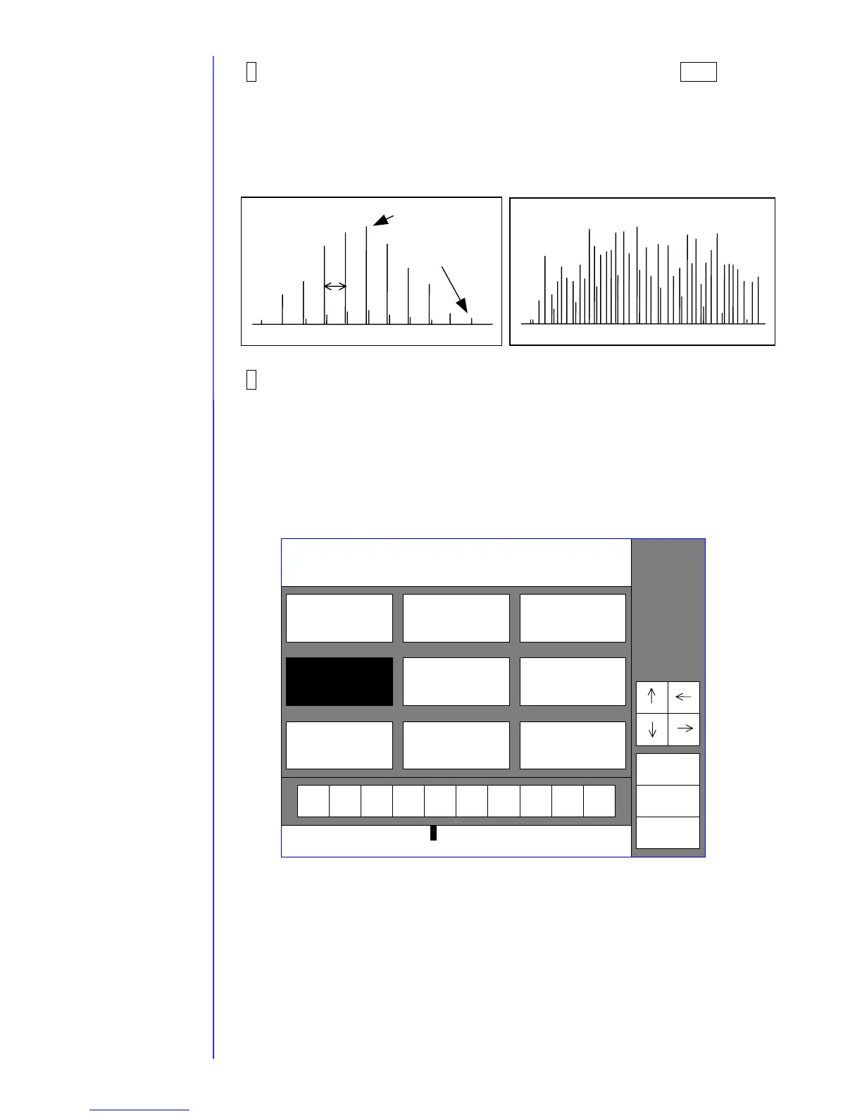
Using the oscilloscope, confirm that the voltage of TP1 (APH signal) on the EZJ94
board is from 8 to 10 V as the maximum voltage, 2 V or less as the minimum voltage,
and is “normal” as shown in the following figure.
4 When the automatic adjustment is not normally completed or the
waveform is “abnormality”, confirm that the periphery of the gutter part is
made dirty with ink or makeup ink. When dirtiness or the like is present,
wash the periphery of the gutter part, surely dry it and then, perform the
automatic-adjustment again.
Numerical values of the auto phase gain value can also be input by a ten-key. To the
value set at present, if the auto phase gain value is set large, the gain becomes high,
whereas if it is set small, the gain becomes low. When the “Back” key is input, the
auto phase detection voltage is output and the auto phase gain value is reflected.
Normal
Maximum voltage
from 8 to 10 V,
minimum voltage 2 V
or less
Noise small
Noise large
10ms
With respect to positions of
the board and the test pin,
refer to " 3.3.2 EZJ94 board".
Auto-phase gain value [ 3 0 ] ( 2 – 62 )