3-16
- When using the external dedicated power supply: Irrespective of the output form of the
rotary encoder, set as shown in the following table depending on the power supply voltage.
Power supply voltage SW2 - 1 SW2 - 2 SW2 - 3 SW2 - 4
DC12V OFF ON ON OFF
DC24V OFF OFF ON OFF
- Check point/LED
Reference
number
Name Content
TP1 GND Reference ground of IJ printer side circuit
TP2 Floating GND Reference ground of external part (conveyer side)
photo coupler insulation circuit
TP3 Print target detector- N Printed target detector input
(“L” at signal inputting)
TP4 Printing output-N Printing signal output (“L” at signal outputting)
TP5 Fault-P Fault output (“H” at fault)
TP6 Warning-P Warning output (“H” at warning)
TP7 Encoder-N Encoder input (“L” at signal inputting)
TP8 RD External communication (receiving data)
TP9 SD External communication (transmitting data)
LED1 Print target detector
input
When the Print target detector is ON, it is lighted.
LED2 Printing stop input When the printing stop signal input is ON, it is lighted.
LED3 Rotary encoder input When the rotary encoder signal input for product
speed matching is ON, it is lighted.
LED4 Deflection voltage
ON/OFF input
When the deflection voltage ON/OFF signal input is
ON, it is lighted.
LED5 Reverse direction
printing input
When the reverse direction printing signal input is ON,
it is lighted.
LED6 Printing output When the printing-in-progess/printing-completed
signal output is ON, it is lighted.
LED7 Run input When the run signal input is ON, it is lighted.
LED8 Reset input When the reset signal input is ON, it is lighted.
LED9 Stop input When the stop signal input is ON, it is lighted.
LED10 Online output When the online output is ON, it is lighted.
[Note at the replacement]
- When replacing boards, be sure to turn off the power.
- Perform the setting of SW1 and 2.
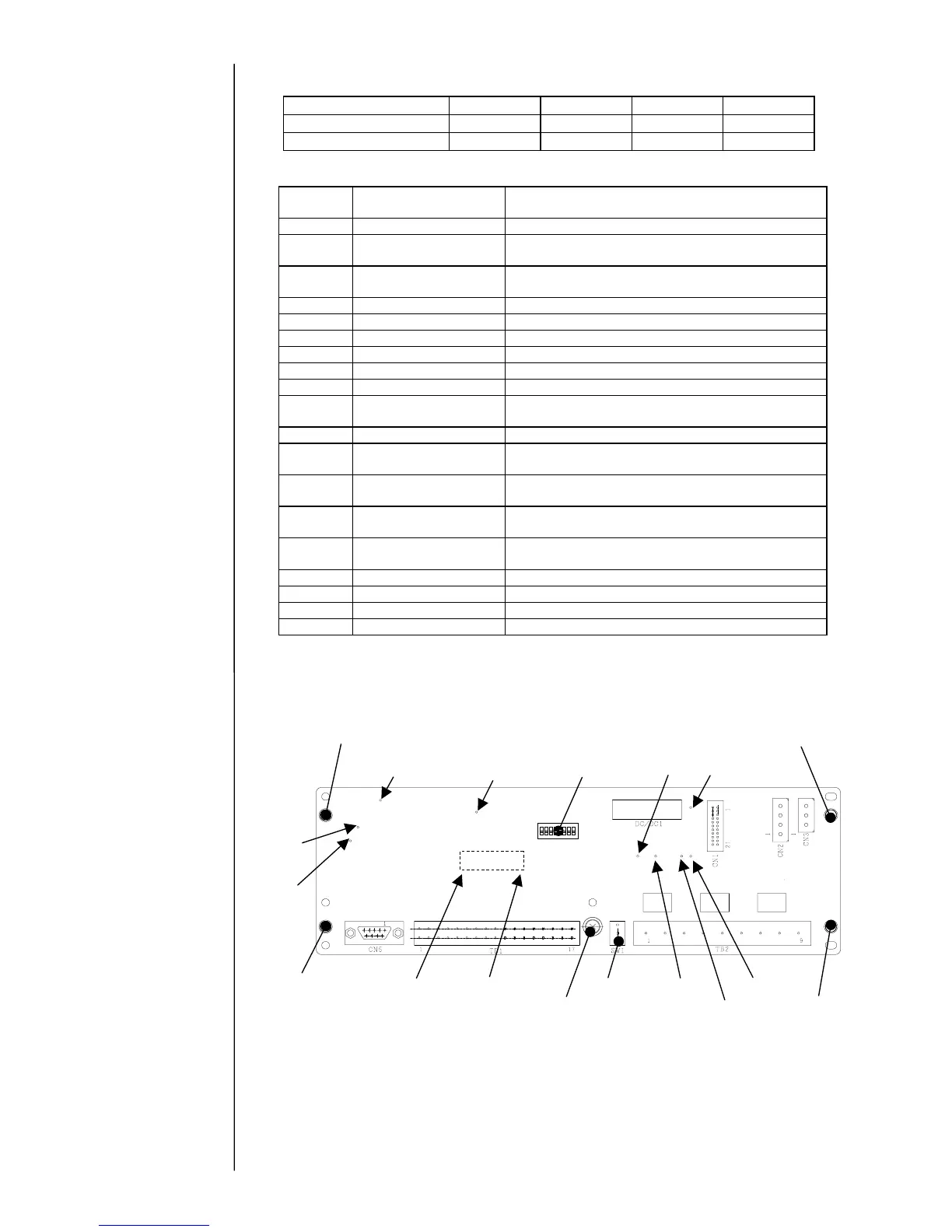
[EZJ95 board external view]
SW1
TP6
TP2
LED1 – LED10
SW2
TP7
TP1
TP4
TP3
TP8
TP9
Five fixing screws
TP5
Five fixing screws
Five fixing screws Five fixing screws
Five fixing screws