10 ELECTRIC WIRING
10.1 GENERAL CHECK
1 Ensure that the eld-supplied electrical components (mains
power switches, circuit breakers, wires, connectors and wire
terminals) have been properly selected according to the
electrical data indicated. Make sure that they comply with
national and regional electrical codes.
2 Following the Council Directive 2004/108/EC(89/336/EEC),
relating to electromagnetic compatibility, next table indicates:
Maximum permissible system impedance Z
max
at the
interface point of the user’s supply, in accordance with
EN61000-3-11
MODEL Z
max
(Ω) MODEL Z
max
(Ω)
RAS-4HVNC1E - RAS-4HNC1E -
RAS-5HVNC1E - RAS-5HNC1E -
RAS-6HVNC1E - RAS-6HNC1E -
3 Harmonics situation of each model regarding IEC 61000-3-2
and IEC 61000-3-12 is as follows:
MODELS SITUATION REGARDING
IEC 61000-3-2 AND IEC 61000-3-12
Ssc “xx”
MODELS
Ssc “xx”
(KVA)
Equipment complying with IEC
61000-3-2
(professional use)
RAS-(4-6)HNC1E
Equipment complying with IEC
61000-3-12
RAS-(4-6)HVNC1E -
4 Check to ensure that the power supply voltage is within +/-
10% of the rated voltage.
5 Check to ensure that power supply has an impedance low
enough to warranty not reduce the starting voltage more
than 85% of the rated voltage.
6 Check to ensure that the ground wire is connected.
7 Connect a fuse of specied capacity.
? NOTE
Checkandtesttoensurethatifthereismorethanonesourceofpower
supply,thatallareturnedOFF.
! CAUTION
• Checktoensurethatscrewsforterminalblockaretightlytightened.
• Checktoensurethattheindoorfanandtheoutdoorfanhavestopped
beforeelectricalwiringworkorperiodicalcheckisperformed.
• Protectthewires,drainpipe,electricalparts,fromratsorothersmall
animals.Ifnotprotected,ratsmaydamageunprotectedparts,andat
theworst,arewilloccur.
• Wrapthe accessorypackingaroundthewires,and plug thewiring
connectionholewiththesealmaterialtoprotecttheproductfromany
condensedwaterandinsects.
• Tightlysecurethewireswiththecordclampinsidetheindoorunit.
• Lead the wires through the knockout hole in the side cover when
usingconduit.
• Securethecable of theremotecontrol switch withthecord clamp
insidetheelectricalbox.
• Electricalwiringmustcomplywithnationalandlocalcodes.Contact
yourlocalauthorityinregardstostandards,rules,regulations,etc.
• Checkthatthegroundwireissecurelyconnected.
• Connectafuseofspeciedcapacity.
! DANGER
• Donotconnectofadjustanywiringorconnectionsunlessthe
mainpowerswitchisOFF.
• Check that the earth wire is securely connected, tagged and
lockedinaccordancewithnationalandlocalcodes.
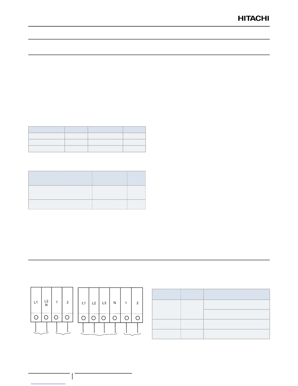
10.2 ELECTRICAL WIRING CONNECTION FOR OUTDOOR UNITS
The electrical wiring connection for the outdoor unit is shown in gure below:
Power supply
1~ 230V
RAS-(4-6)HVNC1E
RAS-(4-6)HNC1E
Control cable
(5V)
Control cable
(5V)
Power supply
3N~ 400V
Table for Terminal Connection between units
Wiring System
Units type
Connection of terminals
Power Supply DC inverter
O.U. to O.U.
L1 to L1, L2 to L2, L3 to L3, N to N
I.U. to I.U.
L1 to L1, N to N
Operating DC inverter
O.U. to I.U. or I.U. toI.U.
1 to1, 2 to 2
Remote Control DC inverter
I.U. to I.U.
A to A, B to B
O.U.: Outdoor Unit; I.U.: Indoor unit
ELECTRIC WIRING

 Loading...