Multi-Row and Multiple Installations
Mount the airow guide and provide sufcient space on both right and left sides
When using airow guide (AG-335A,
optional), check that the discharged air is not
short-circuited to the air inlet side
A B
0 < L ≤ 1/2H 1/2H < L≤ H 0 < L ≤ 1/2H 1/2H < L≤ H
Min. 600 Min. 1400 Min. 300 Min. 350
When L > H use a base for outdoor unit to
make L ≤ H.
Close the base not to allow the outlet air
bypassed.
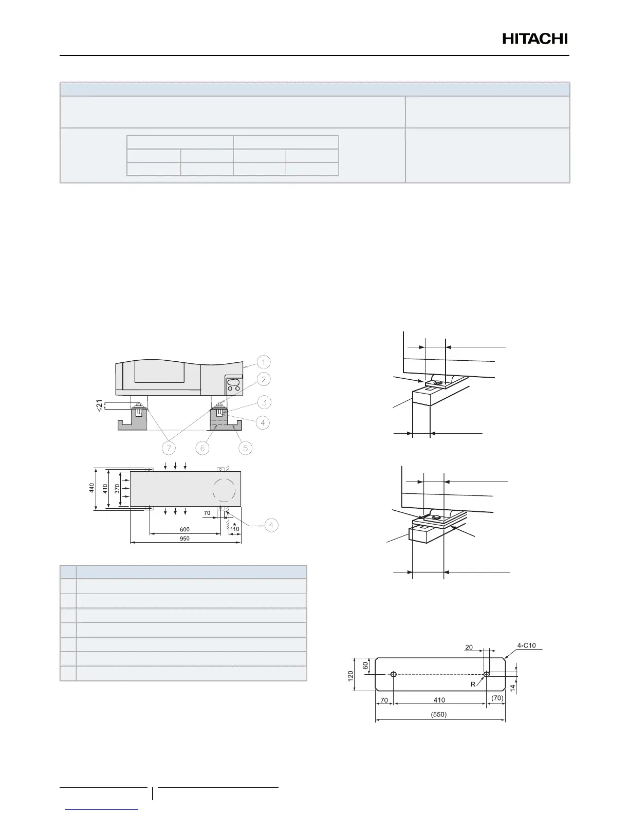
7.1.2 Installation place provision
Concrete Foundation
1 Foundation could be on at and is recommended be 100-
300 mm higher than ground level.
2 Install a drainage around foundation for smooth drain
3 When installing the outdoor unit x the unit by anchor bolts
of M10.
4 When installing the unit on a roof or a veranda, drain water
sometimes turns to ice on a cold morning. Therefore, avoid
draining in an area that people often use because it is
slippery.
* Space for downward piping space
Nº Description
Outdoor Unit
Cut this portion of bolt If not, it’s difcult to remove Service Cover
Mortar Hole (Ø100xDepth 150)
Anchor Bolt M10 (Ø12.5 Hole)
Drainage (Wide 100xDepth 150)
Drainage
Vibration-proof rubber
? NOTE
Whenthemark*dimensionissecured,pipingworkfrombottomsideis
easywithoutinterferenceoffoundation.
5 The whole of the base of the outdoor unit should be installed
on a foundation. When using vibration-proof mat, it should
also be positioned the same way. When installing the
outdoor unit on a eld supplied frame, use metal plates to
adjust the frame width for stable installation as shown in
below gure.
70 mm
Base width of outdoor unit
Outdoor unit
is unstable
Frame
60mm
Frame width (Field supplied)
INCORRECT
CORRECT
Outdoor unit
is stable
70 mm
Base width of outdoor unit
Frame
100mm or more
Metal plate
Recommended Metal Plate Size
- (Field-Supplied) Material: Hot-Rolled Mild Steel
- Plate (SPHC) Plate Thickness: 4.5 T
UNITS INSTALLATION

 Loading...