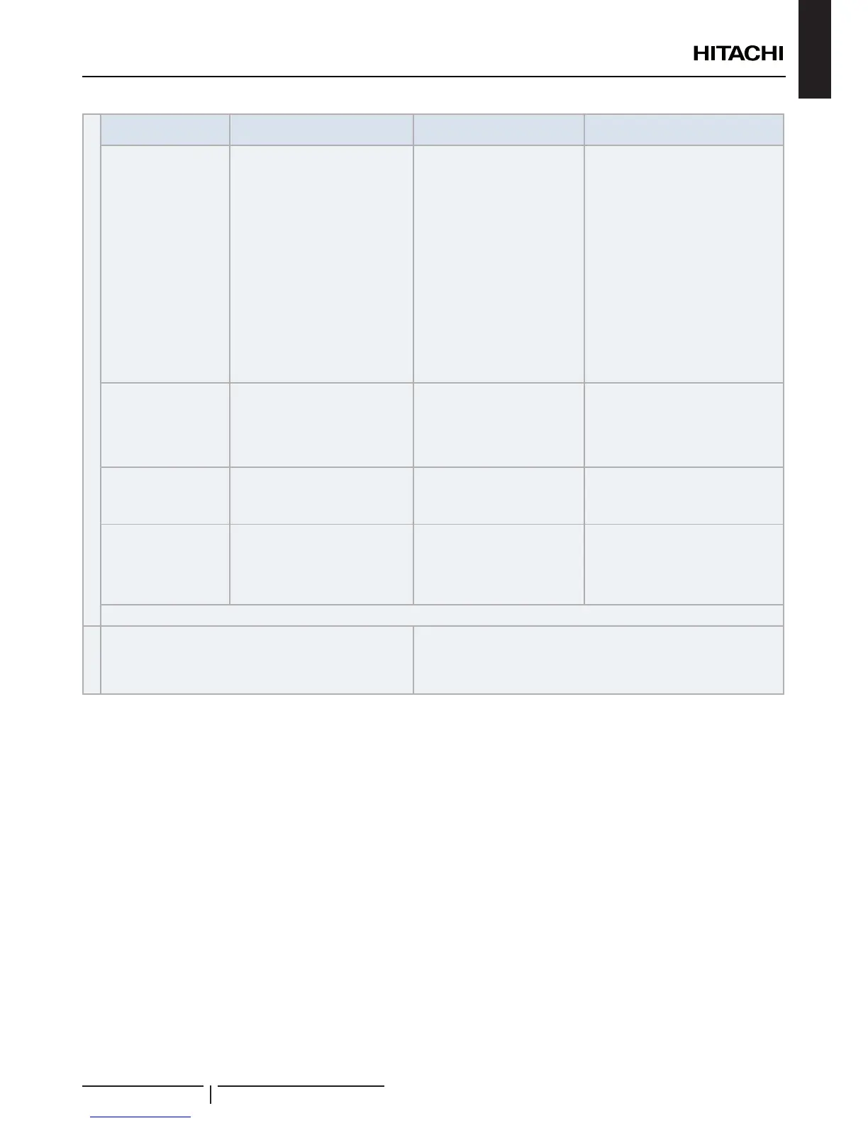
Remote Control
Switch Indication
Unit Condition Wrong Portions
Inspection Points after Power
Source OFF
The operation lamp
ickers. (1 time/1 sec.)
And the Unit Nº and
Alarm Code “03” icker
The unit does not start.
The power source of Outdoor
Unit in not turned ON.
The connecting wires of operating
line are incorrect or loosened.
1 Connecting Order of each Terminal
Board.
2 Screw fastening of each Terminal
Boards.
? NOTE
Recovering method of FUSE for
operating circuit. There is a fuse
(FUSE4 on Indoor Unit PCB1, EF1
on Outdoor Unit PCB1) to protect
operating circuit on the PCB, when
the power lines are connected to
operating lines. If fuse is melted,
operating circuit can be recovered
oncebysettingthedipswitchonthe
PCBasshownin
The operation lamp
ickers. (1 time/2 sec.)
The unit does not start.
Remote control cable is broken.
Contact of connectors is not
good.
The connection of remote control
cable is incorrect
This is the same as item 1 and 2
Indication of Flicker
except above
The unit does not start, or start once
and then stops
The connection of thermistor or
other connectors are incorrect.
Tripping of protector exists, or
else.
Check by the abnormality mode table
in the Technical Catalogue (Do it by
service people).
The operation lamp
Flickers. (1 Time/1s)
Unit Nº 00, Alarm Code
and Unit Code 00
icker
The unit does not start.
The connection of the remote
control cable between Indoor
Units is incorrect.
Check by the abnormality mode table in
the Technical Catalog (Do it by service
people).
Back to after checking
Instructions fot the recovery when the fuse of the transmission
circuit is blown out:
1 Correct the wiring to the terminal board.
2 Set the 1st pin of DSW7 on the indoor unit PCB to ON.
COMMMISSIONING

 Loading...