Basic Operation - Unbalance Display MC10 HS
4 - 8
4.5 Unbalance Display
After the program start or after pressing the "Unbal-
ance Display" key, the unbalance display appears:
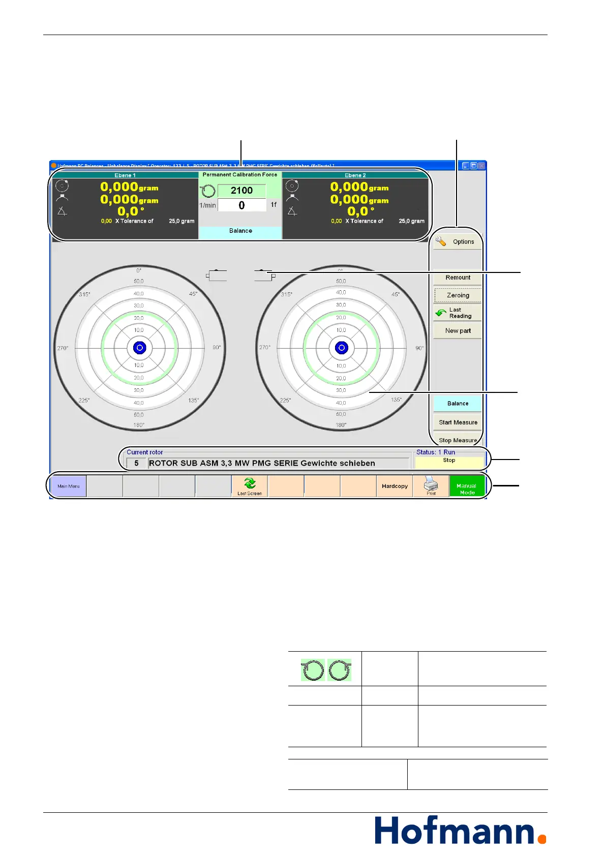
Fig. 4-2: Unbalance Display
1 - Indication of unbalance amount and angle,
type of calibration, direction of rotation, rotation-
al speed
2 - Command Keys
3 - Unbalance display mode (here: 2-plane)
4 - Indication of unbalance in polar diagram
5 - Indication of currently selected rotor and status
display
6 - Command Bar
Indicator RH / LH rotation
1/min (RPM) Indicator Currently measured speed
1f
2f
Indicator direct speed
optional - double sample rate
for diagnosis
Current rotor Indication of currently selected
rotor type