Operation - Remount Balancing (Option) MC10 HS
5 - 20
For universal shaft drive 5.5 Remount Balancing (Option)
Refer to chapter 7 Remount balancing.
Rotor data set has been created.
The machine is ready for operation and set up
on the rotor.
5.5.1 Remount Balancing
Remount balancing is used to distinguish between
the unbalance of auxiliary devices (e.g. universal
shafts) and the unbalance of the workpiece (rotor).
Load rotor into the machine.
Couple rotor to universal shaft.
Close protective shroud.
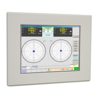
Carry out measuring run.
Press "Index. Bal." key (1).
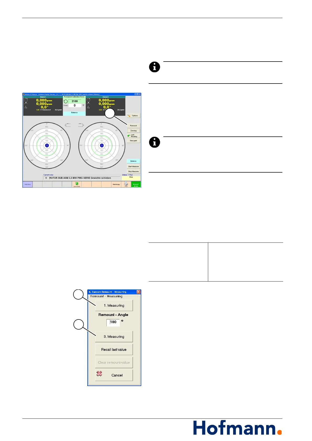
Enter remount angle:
Press "1. Measuring" key (2).
Open protective shroud.
Uncouple rotor from universal shaft.
Turn rotor counter-clockwise by the value of the
entered angle with respect to the universal
shaft.
Couple rotor to universal shaft.
Close protective shroud.
Carry out measuring run.
Press "Index. Bal." key (1).
Press "2. Measuring" key (3).
Open protective shroud.
Uncouple rotor from universal shaft.
Remount angle Angle, to which the location of the
workpiece is indexed, which was
at 0°. The counting direction of
the angle scale is applicable (re-
fer to Options). The value should
be between 90° and 270°.