MC10 HS Operation - Editing Rotor Data
5 - 9
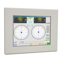
5.2.13 Setup Rotor Data - Correction
Main menu \ Rotor settings.
Select "Correction" tab.
Enter values or change settings:
5.2.13.1 Unbalance Display
Polar correction
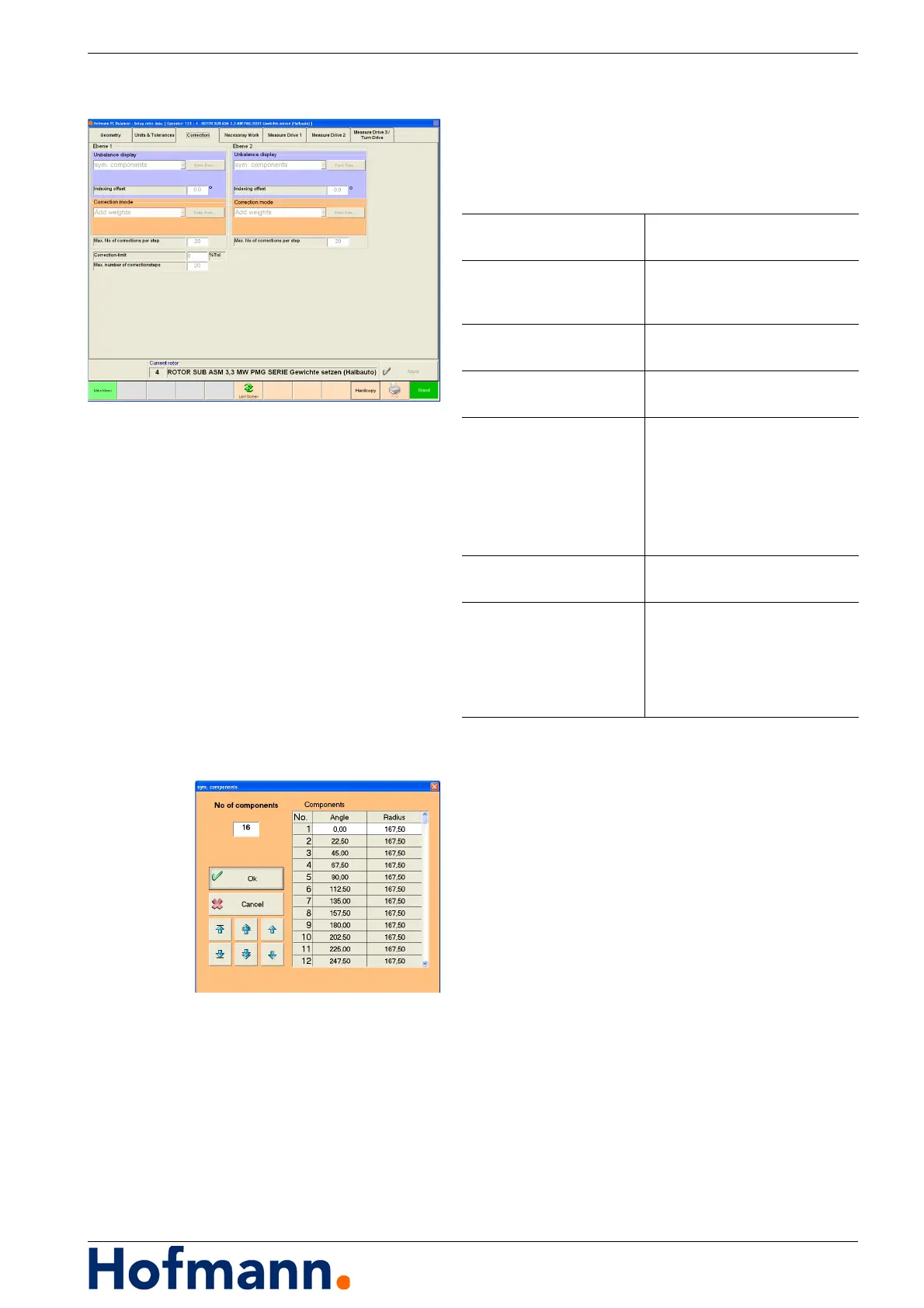
Symmetrical components
Select "Sym. components".
Press "Enter values" key.
Enter number of components.
Enter angle and radius of first component.
The system will calculate all other components.
Accept with "Ok".
Unbalance Display Select polar or component cor-
rection
Indexing offset Offset correction position (grip-
per)
with respect to 0°-position
Correction mode Select type of unbalance cor-
rection
Max. number of correc-
tions per step
e.g. max. number of drillings per
unbalance correction step.
Correction limit Correction target in percent of
tolerance.
Entry (0 % - 90 %)
i.e. Tolerance 100gmm
Correction limit 30 %
Correction to 30gmm residual
unbalance
Max. number of correction
steps
Max. number of unbalance cor-
rection steps.
Weight scanning offset Angular offset between 0°-posi-
tion and scanning position (for
scanning of sliding weight posi-
tion).
The values should be set the
same for each rotor!