Basic Operation - Unbalance Display MC10 HS
4 - 12
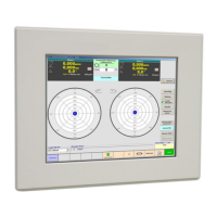
4.5.2.3 Display settings
Unbalance Display \ Options.
Select "Display Settings" tab.
Enter values or change settings:
Press "Ok" or "Cancel" key.
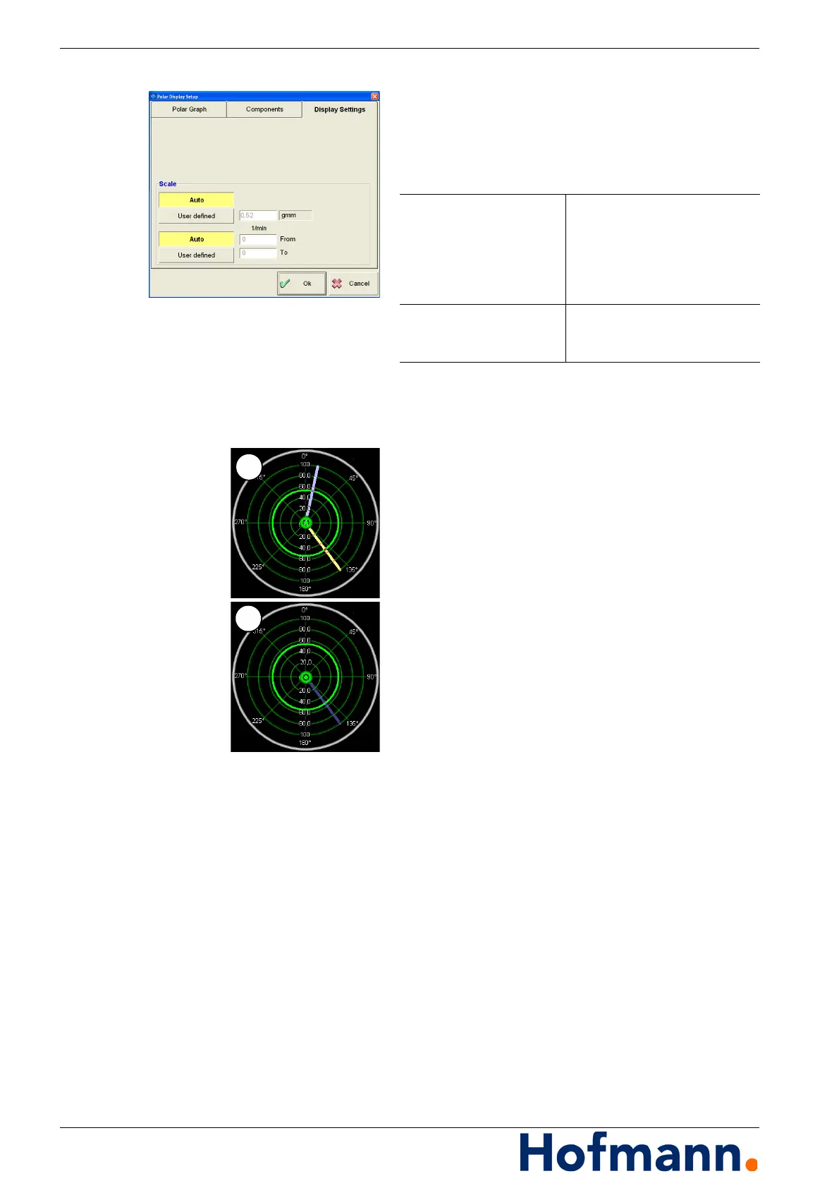
4.5.3 Indexing Indicator (Option)
The unbalance measuring system supports the
user in finding the exact angular position of the
unbalance.
For this purpose, radial lines (1) synchronised
with the angular reference system of the bal-
ancing machine are shown in the polar dia-
gram. These lines will follow the rotation of the
rotor.
Once the correct angular position is reached,
the radial line changes colour (2).
For the compensation type "drilling", the re-
quired drilling depth is also indicated.
For precise transfer of the angular position to
the rotor, the line laser is switched on once the
correct position is reached.
Scaling Auto /
User defined
(top)
Let scaling of the polar display
for both planes be adapted au-
tomatically or define as requi-
red.
Enter maximum value of sca-
ling.
Scaling Auto /
User defined
(bottom)
without function (incl. speed in-
put)