MC10 HS Operation - Remount Balancing (Option)
5 - 21
Remove rotor.
Remount balancing and the determination of tool er-
ror compensation values is now complete. The tool
error compensation values are included in the dis-
played measurement values.
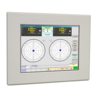
5.5.2 Deleting Tool Error Compensation
Values
Press "Index. Bal." key (1).
Press "Clear remount-value" key (2).
The tool error compensation run is deleted. No tool
error compensation values are included in the dis-
played measurement values.
5.5.3 Reading Tool Error Compensation
Values
Press "Index. Bal." key (1).
Press "Recall last value" key (3).
The tool error compensation run is now read. Tool er-
ror compensation values determined during the last
compensation run are included in the displayed
measurement values.
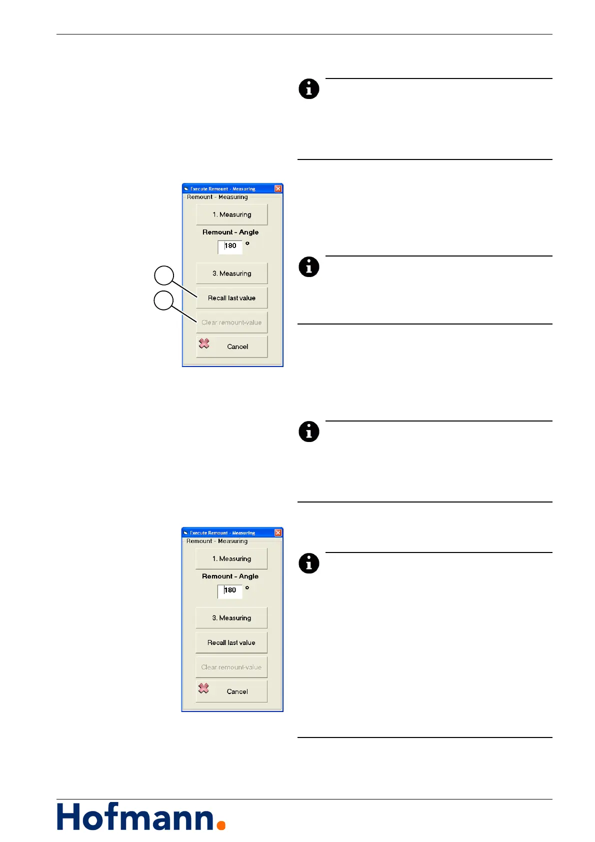
5.5.4 Multiple Remount Balancing
The unbalance measuring system provides the pos-
sibility of multiple remount balancing.
In order to obtain most accurate tool error compensa-
tion values, rotors are rotated by 180°.
However, there are rotors and adaptors, where this is
not possible; e.g. a rotor fixed to the adaptor by three
bolts. The second measuring run is then carried out
for the rotor rotated by 120°.
In this case, a second measuring run is now possible
for a remount angle of 240°. The values obtained
from this measurement are averaged with the previ-
ously obtained ones.
For multiple remount balancing, the remount
angle must also be between 90° and 270°. The
0° position cannot be repeated.