Basic Operation - Unbalance Display MC10 HS
4 - 10
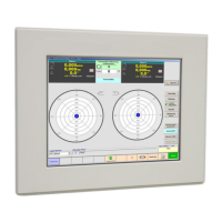
4.5.1 Displaying Unbalance
Amount and angle Magnitude of unbalance in unbalance and
weight unit
Unbalance location in degrees (°)
Meaning of the different colours and numbers:
A red indication can have several reasons:
- The unbalance cannot be compensated with the
given possibilities (i.e. drilling diameter and/or max.
drilling depth, material density). The unbalance is
simply too big.
- The initial unbalance exceeds the correction limit
(refer to Chapter 5.2.12 - Setup Rotor Data - Units
and Tolerances).
- The max. number of correction steps has been
reached (refer to Chapter 5.2.13 - Setup Rotor Data -
Correction).
- Repeat measurements are carried out. However,
the MC10 assumes that an unbalance correction is
carried out after each measuring run.
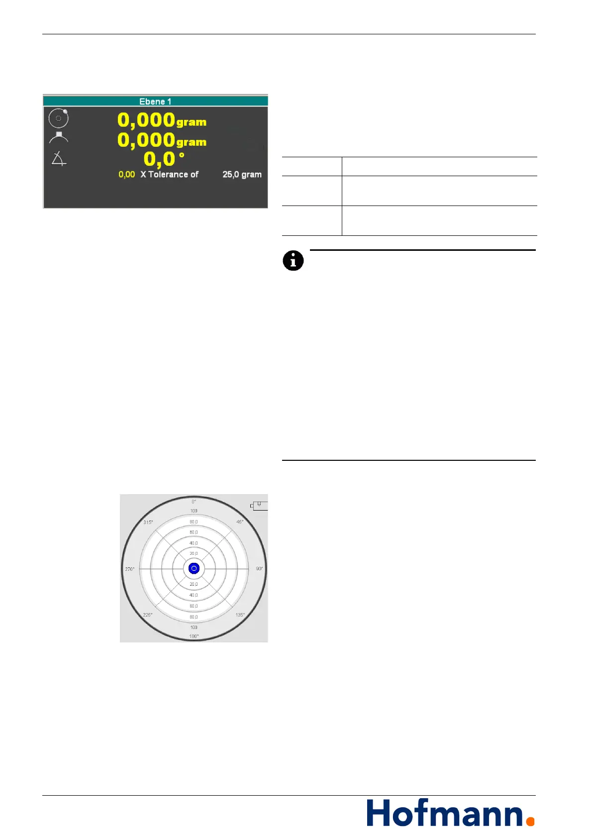
Polar diagram Unbalance magnitude and position
Display of tolerance limit (green ring).
With the corresponding setting (i.e. unbalance
display in components with compensation type
"drilling") you can obtain a direct indication of
the components and/or the compensation val-
ues in a table, instead of the indication of the
amount and angle, simply by touching a polar
diagram on the screen.
You can revert to the standard display by
touching the table.
Green Rotor unbalance in tolerance.
Yellow
Rotor unbalance out of tolerance,
correction necessary and possible.
Red
Rotor unbalance exceeds correction limits,
no correction.