2-76
[9] JOINT A
[10]
SPEED SENSOR
TUBE A
[6]
WIRE
BAND
[5] SPEED SENSOR
TUBE C
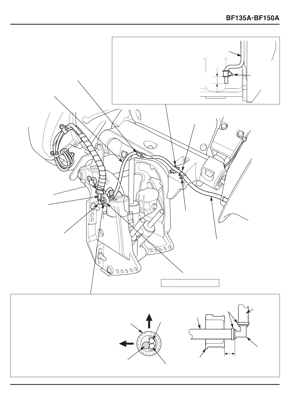
[3] SPEED SENSOR TUBE PLATE
Install the speed sensor tube plate
so that the distance between the
end of the plate and the end of the
speed sensor tube B is 15 – 20 mm
(0.6 – 0.8 in).
[8] SPEED SENSOR TUBE B
• Pass the trim angle sensor wire,
power tilt motor wire and the speed
sensor tube B through the hole in the
motor cord bushing as shown.
• Install the speed sensor tube B so that
the distance between the end of the
motor cord bushing and the end of
the speed sensor tube B is 10 – 15 mm
(0.4 – 0.6 in).
[3]-1
SPEED SENSOR
TUBE B
[4]
TUBE CLIP B8
[3]-1
SPEED
SENSOR
TUBE
PLATE
[2]
SPEED SENSOR
TUBE PLATE
15 – 20 mm
(0.6 – 0.8 in)
[1]
SPEED SENSOR
TUBE B
[7] MOTOR CORD BUSHING
[8]-1
MOTOR
CORD
BUSHING
[8]-1
MOTOR
CORD
BUSHING
INSTALLATION: P. 2-63
[8]-9
JOINT A
[8]-3
TRIM
ANGLE
SENSOR
WIRE
[8]-4
POWER TILT
MOTOR WIRE
[8]-5 SPEED
SENSOR
TUBE B
[8]-5
SPEED
SENSOR
TUBE B
[8]-8
SPEED
SENSOR
TUBE A
10 – 15 mm
(0.4 – 0.6 in)
[8]-7
WIRE
BANDS
[8]-6 REAR
[8]-2
UP
 Loading...