Extinguishing Control Computer 8010 – 19-Inch
18 FB 798955.GB0 / 09.07
3 Control indicator and Alarm counter
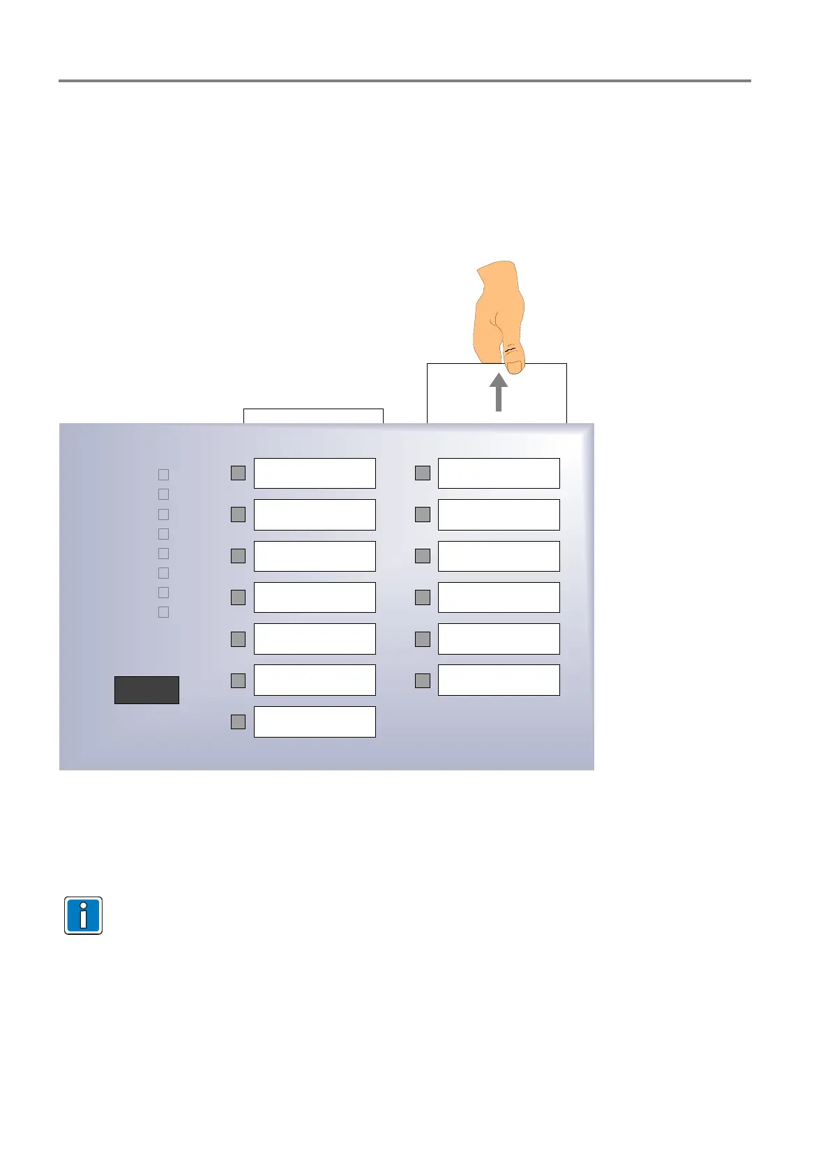
The Extinguishing Control Computer can be equipped with an optional >Control indicator and Alarm counter<
(Part No. 788016).
The LED indicators no. 1 to 13 lit when the corresponding detector zone or output (relating to the customer data
programming) is activated. The description of each output can be edited in the lettering area.
Relay (AE) 1
2
3
4
5
6
7
8
9
10
11
12
13
0 0 0 5
Fan trouble
Common trouble
Emergency
operation
Power trouble
Battery trouble
Ground fault
Trouble 1
Blocking
Fig. 17: Control indicator and Alarm counter
The mechanical alarm counter displays the total quantity of all recognized fire alarms and is incremented with
each new fire alarm.
Resetting the counter to zero - 0000 - is not possible.

 Loading...


