Extinguishing Control Computer 8010 – 19-Inch
34 FB 798955.GB0 / 09.07
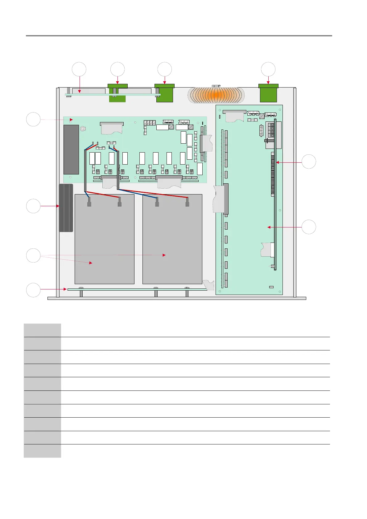
7 Position and operation of the devices
2
4
5
6
7
8 1
3
109
Fig. 25: Position of the devices (Top view with open housing)
c
Mains terminals (L1/N/PE) to connect the 230V AC mains voltage
d
Processor board (mounted upright on the zone board)
e
Zone board (series 2 or series 3)
f
Operating and indicating panel board
g
Batteries max. 2 x 12 V DC / 12 Ah
h
Fan
i
Power supply and relay board
j
Board with D-SUB connectors to connect the external terminal card (via a 50-pole cable)
k
Terminals for relay 12
l
Terminals for relay 13
 Loading...


