Extinguishing Control Computer 8010 – 19-Inch
46 FB 798955.GB0 / 09.07
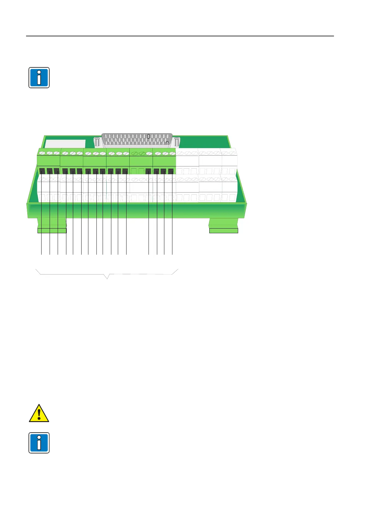
7.4.3 Detector zones 1 to 8
Only fire alarm detector series 9000/9100 may be connected to the detector zone inputs
1 to 8 of the Extinguishing Control Computer 8010- 19-inch series 3 (refer to the appropriate
section “zone board series 2 or series 3”).
Recommended cable: I-Y (St) Y n x 2 x 0,8 mm
Cable length per detector zone: max. 1000 m
123 456789101112
13 14
15161718
19 20
21 22 23 24
25 26
-+
1
-+-+-+-+-+ -+-+
Meldergruppen
23456 78
Fig. 34: Position of the detector zone inputs 1 to 8 on the zone terminal card (type Phoenix / Weco)
Special application fort he detector zones 7 and 8 (operation mode = conventional zone)
Detector zone 7
Operation mode Î Reserve-zone
In the normal operation mode of the >Reserve zone< the >Pilot valve< is used to control the extinguishing agent
tank. In case of an activated >Reserve zone< the >Spare valve> is used instead.
Detector zone 8
Operation mode Î Detector type >Flow control sensor<
This zone input is suited to connect >Flow control sensor< to monitor the pipe system. For this application the
zone input must be programmed with the functionality >Flow control sensor<.
End-of-line resistor : 4,7k
Ω normal / 1kΩ activation
Requirements for automatic detector zones
The activation of a Fire Extinguishing System via automatic fire detector zones requires a >Two-
zone-coincidence< (2ZD) or >Two-detector-coincidence< (2DD).
Programming
The detector zones 1 to 8 are configured with the programming software LKDE from version
V02.00.
 Loading...


