Extinguishing Control Computer 8010 – 19-Inch
FB 798955.GB0 / 09.07 65
8.2 CPU-failure mode
Even in the CPU-failure mode, e.g. failure of the main processor or a trouble in the program memory, the alarm
and triggering functions of the Extinguishing Control Computer can be guaranteed through the >Emergency
operation trouble< and >Emergency operation fire< mode.
For this purpose, the function >Emergency operation fire<
(relay 10) and >Emergency operation trouble<
(relay 11) must be configured with the corresponding jumpers.
In CPU-failure mode, all relays are de-energized and change the switching state except the relay >Emergency
Operation Trouble< (relay 11). The red display and control panel LED >Emergency
operation< is permanently
activated.
Installed and operational detector zones continue to be monitored for the status >Fire<. If a fire is detected, the
relay >Emergency Operation Fire< (relay 10) changes the switching state.
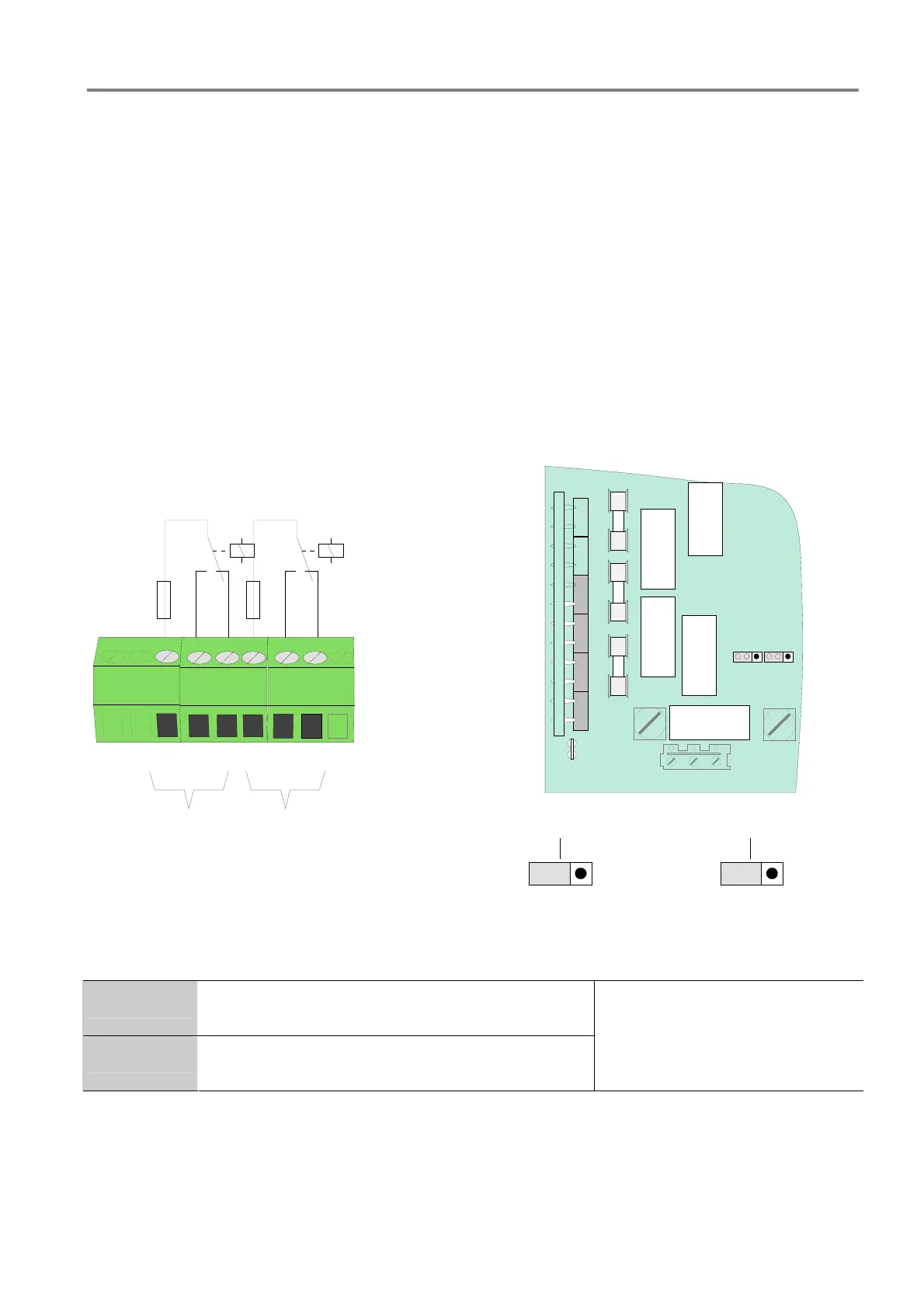
Connection example (Relay terminal card type “Phoenix”)
F2
F3
F4
Emergency
operation
REL10
REL11
T2A
T2A
39
404142434445
NC
NO
C
NC
NO
C
Relay 11
Relay 10
Emergency operation
trouble
J5
inactive active
Emergency operation
fire
J7
inactive active
Fig. 46: Jumper for emergency mode settings (relay 10 and 11)
Relay 10 >Emergency operation fire< or Standard function,
configured with jumper J7
Relay 11 >Emergency operation trouble< or Standard function,
configured with jumper J5
Changeover contact,
contact rating
max. 30 V DC / 2A
 Loading...


