Extinguishing Control Computer 8010 – 19-Inch
36 FB 798955.GB0 / 09.07
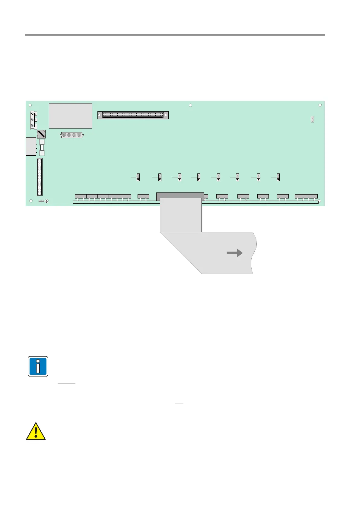
7.2 Zone board - series 2
The zone board - series 2 is designed for connection of eight standard detector zones for automatic detectors
series 9000 and/or 9100. Refer to section 7.4.5 for additional options to connect technical alarm zones.
The alarm zone operating mode (standard or EDD) is set via the associated jumpers (J1 to J8). Mixed operation
on one alarm zone of series 9000 and 9100 automatic fire detectors is not permissible.
N
PE
L1
F1
T4A
X1
X2
X3
F2
T1A
TRAFO PRIMARY
Zone board
Trafo secund.
X16
J9
X4
X5
Internal connection
to zone terminals
Connection processor card
Groung fault
identification
Power voltage
To power supply- and relay card
Std.
EDD
Std.
EDD
Std.
EDD
Std.
EDD
Std.
EDD
Std.
EDD
Std.
EDD
Std.
EDD
Fig. 27: Zone board - series 2 (Part No. 771793) / position of the subassemblies
Terminals
The zone board is fully internal connected with the terminals of the mains supply voltage and the D-SUB board
of the external terminal card connection.
Unused detector zone inputs must be programmed as >unused< in the customer data or
alternatively terminated with an End-of-line resistor.
Do not
connect Fire detectors series 9200 / IQ8Quad.
Mixed operation of automatic fire detectors, and/or technical alarm modules or esserbus
®
transponders in a common detector zone is not
permitted.
When connecting the mains voltage and the protective earth, refer to the instructions in the chapter
“Mains connection and earthing“!
 Loading...


