Extinguishing Control Computer 8010 – 19-Inch
FB 798955.GB0 / 09.07 27
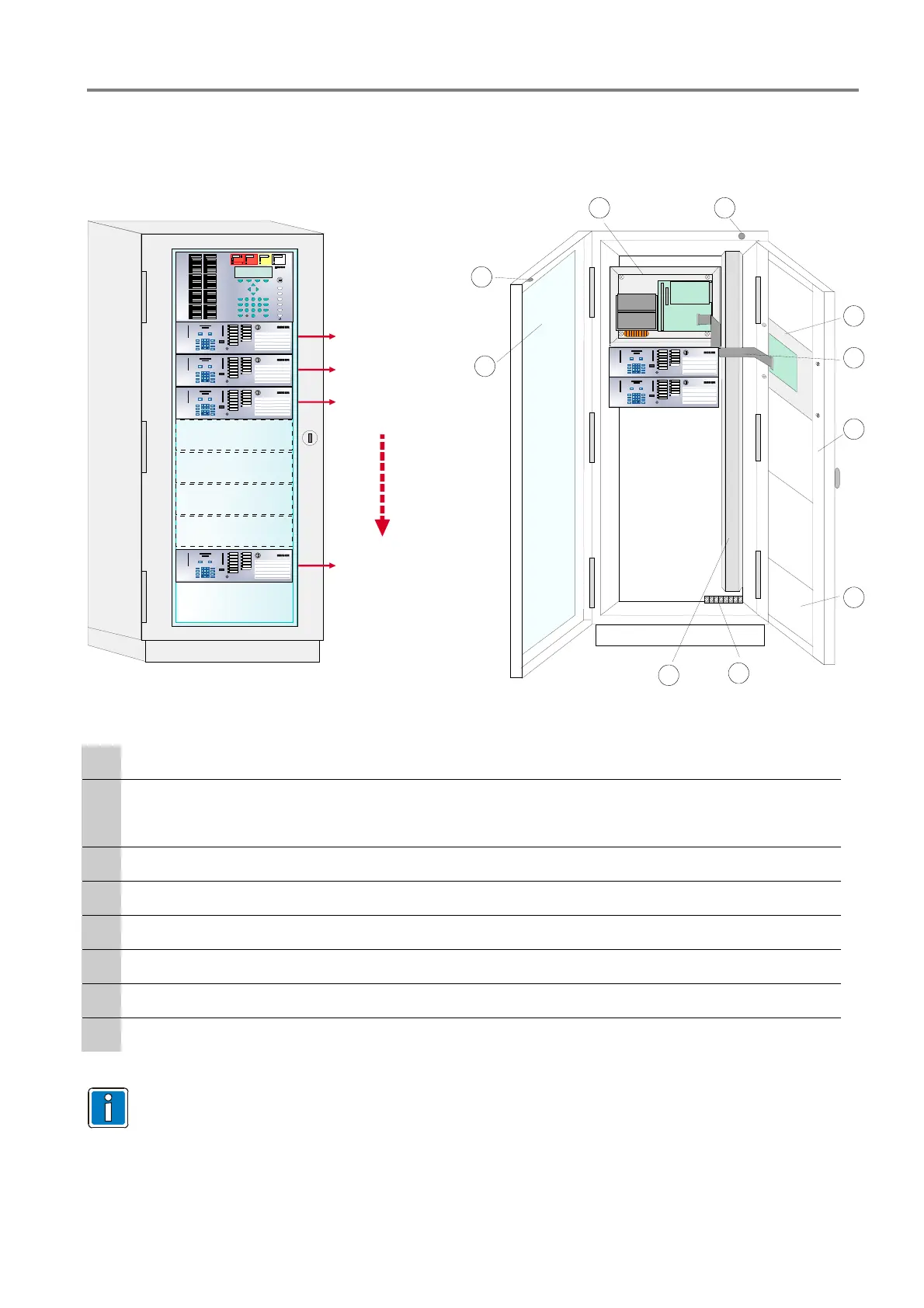
5.2 19-inch rack mounting
The following example shows the installation of an Extinguishing Control Computer in conjunction with a Fire
Alarm Control panel in a common 19-inch rack.
123
456
789
0
Extinguishing area 1
1
2
3
4
5
6
7
8
1
4
7
0
8
5
23
6
9
0 0 0 5
1
4
7
0
8
5
23
6
9
0 0 0 5
1
4
7
0
8
5
23
6
9
0 0 0 5
1
4
7
0
8
5
23
6
9
0 0 0 5
Extinguishing area 2
Extinguishing area 3
Extinguishing area 8
2
1
3
4
6
7
8
2
9
5
1
4
7
0
8
5
23
6
9
0 0 0 5
1
4
7
0
8
5
23
6
9
0 0 0 5
Fig. 20: Front view of the 19-inch rack mounting (Example with Fire Alarm Control Panel)
c
Cabinets door with security lock and protective glass
d
Door contact – used to disconnect a connected manned centre link (MCL)
e
Fire Alarm Control Panel (FACP) without housing/cover or operating panel
f
Remote indicating and operating panel of the FACP mounted in the cabinets door
g
Ribbon cable wiring between FACP and the indicating and operating panel
h
19-inch swivel frame to mount the remote indicating and operating panels
i
19-inch- cover plate (2 HE, 3 HE, 5 HE, 9 HE )
j
Terminals for the 230 V AC mains voltage
k
Cable duct
The batteries must be mounted in the appropriate place inside the housing of the Extinguishing
Control Computer. Observe the required orientation of the battery placement
(refer to battery label).
The connection of external batteries, e. g. placed on the cabinets floor is not permitted.

 Loading...


