Extinguishing Control Computer 8010 – 19-Inch
28 FB 798955.GB0 / 09.07
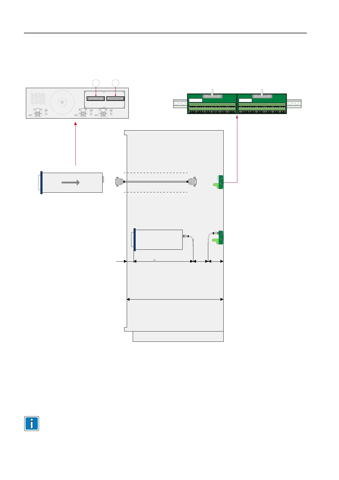
The housing of the Extinguishing Control Computer must be inserted in an appropriate 19-inch mounting slot of
the cabinet and fastened by the 4 screws (see front side) from the front. To connect the zones and relay a
separate 50-pole terminal card is required. This terminal cards are mounted on a C-rail in the back of the
cabinet and connected via a D-SUB cable to the appropriate connectors on the back side of the Extinguishing
and Control Computers housing.
1 2
max. 2 m
100 mm
> 500 mm
150
mm
X
X = cabling space
800 mm recommended
Fig. 21: Wiring to the external C-rail terminal
Cabinet requirements
It is highly recommended to use a cabinet (19-inch rack) with a mounting depth of 800 mm. The to handle bars
on the housings front side require a mounting space from min. 100 mm measured to the cabinets door.
Ensure a sufficient space for the C-rail terminal connection behind the housing. Connect cable with a suited
bending to avoid a damage of the cable.
All required terminals are located on the external terminal card. The connection of cables to the
separate circuit boards inside the housing of the Extinguishing Control Computer 8010 is not
necessary.
 Loading...


